Download
1 / 8
80 likes | 90 Views
This case discusses the presence of ribbon-like artifacts observed in 2D fast spin echo MR images of the pelvis acquired using a 12-channel phased array coil. The most likely explanation for these artifacts is peripheral signal artifacts, caused by signal generated outside the prescribed field-of-view being detected by the receiver array and aliased into the image.

E N D
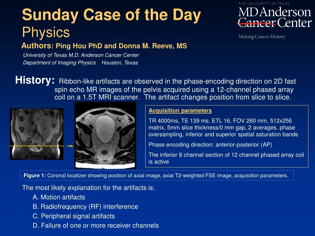
History:Ribbon-like artifacts are observed in the phase-encoding direction on 2D fast spin echo MR images of the pelvis acquired using a 12-channel phased array coil on a 1.5T MRI scanner. The artifact changes position from slice to slice. Sunday Case of the Day Physics • The most likely explanation for the artifacts is: • A. Motion artifacts • B. Radiofrequency (RF) interference • C. Peripheral signal artifacts • D. Failure of one or more receiver channels Authors: Ping Hou PhD and Donna M. Reeve, MS University of Texas M.D. Anderson Cancer Center Department of Imaging Physics Houston, Texas Acquisition parameters TR 4000ms, TE 139 ms, ETL 16, FOV 260 mm, 512x256 matrix, 5mm slice thickness/0 mm gap, 2 averages, phase oversampling, inferior and superior spatial saturation bands Phase encoding direction: anterior-posterior (AP) The inferior 8 channel section of 12 channel phased array coil is active Figure 1: Coronal localizer showing position of axial image, axial T2-weighted FSE image, acquisition parameters.
History:Ribbon-like artifacts are observed in the phase-encoding direction on 2D fast spin echo MR images of the pelvis acquired using a 12-channel phased array coil on a 1.5T MRI scanner. The artifact changes position from slice to slice. Sunday Case of the Day Physics • The most likely explanation for the artifacts is: • A. Motion artifacts • B. Radiofrequency (RF) interference • C. Peripheral signal artifacts • D. Failure of one or more receiver channels Authors: Ping Hou PhD and Donna M. Reeve, MS University of Texas M.D. Anderson Cancer Center Department of Imaging Physics Houston, Texas Acquisition parameters TR 4000ms, TE 139 ms, ETL 16, FOV 260 mm, 512x256 matrix, 5mm slice thickness/0 mm gap, 2 averages, phase oversampling, inferior and superior spatial saturation bands Phase encoding direction: anterior-posterior (AP) The inferior 8 channel section of 12 channel phased array coil is active Figure 1: Coronal localizer showing position of axial image, axial T2-weighted FSE image, acquisition parameters.
Findings:Upon review of the images to determine the cause of the artifact, it was noted that the acquired slices were located near the most inferior portion of the volume of interest, where reduced signal intensity was apparent on localizer images. Only the lower section of the phased-array was active (coil configuration: HD Body Lower). The artifact changed position from image to image within the same axial series as shown in figure 2. To prevent the peripheral signal from wrapping into the image, the axial T2 series was repeated, changing the direction of phase encoding to right-left (RL) (figure 3). Phase encoding direction: AP #23 #33 #37 Slice #37 Slice #33 Figure 2: Coronal localizer (FOV 40cm) showing positions of axial slices 23, 33, 37. Phase encoding direction: RL Slice #23 Figure 3: Axial T2-weighted FSE image: phase encoding direction changed to right-left.
Diagnosis:C. The correct answer is peripheral signal artifacts. These artifacts occur when signal generated outside the prescribed field-of-view (FOV) is detected by the receiver array and aliased into the image in the phase-encoding direction. These artifacts can occur with multi-channel phased array coils when the active area of the array does not match the size or position of the FOV.
A. Motion artifacts: While motion artifacts occur in the phase-encoding direction and are commonly seen in clinical MR images, they can be ruled out since the observed artifacts in this case do not appear as replications (ghosts) of flow or moving anatomy. D. Failure of one or more receiver channels: Failure of a receive channel would result in signal loss and appear as dark shading or low SNR in the same anatomical region of the images within the series. Since the images in this exam exhibit uniform signal intensity we can eliminate channel failure as the cause of the artifacts. Coil quality control testing that includes SNR determination for all channels in a multi-channel array can be used to verify that all channels are working properly. B. RF interference: In a clinical environment there are numerous potential sources of radiofrequency interference, either from sources outside the scan room (and therefore outside the Faraday cage), or from equipment inside the scan room. This interference produces linear artifacts (often called “zipper” artifacts) oriented parallel to the phase-encoding direction. However, RF interference typically occurs at a particular frequency or range of frequencies, and therefore would not be expected to change position from slice to slice within a series. Discussion: The most likely explanation for the artifacts is: A. Motion artifacts B. Radiofrequency (RF) interference C. Peripheral signal artifacts D. Failure of one or more receiver channels
Peripheral signal artifacts are referred to by a number of names, including annefact, foldover, star and cusp artifact, among others4. The artifacts occur when signal is detected from a region outside of the imaging FOV. When the signal frequency matches the frequency being encoded, it is aliased into the image. The artifact can have different appearances, such as star, feather-like, or ribbons. In FSE imaging the artifact appears as a series of repeated signals in the phase-encoding direction. Hardware and software techniques to solve the problem of peripheral signal artifacts are under investigation4. One commercially available approach is adaptive phased-array (APA) coils. Currently, eliminating these artifacts in clinical images can be a challenge. Some approaches to reducing or eliminating the artifact are: Ensure that the appropriate coil configuration is chosen for the anatomical area of interest. Ensure that the active area of the array is aligned with the size and position of the imaging volume. Carefully place saturation bands relative to the prescribed FOV or consider removing them. In some cases the artifact may be eliminated by swapping phase and frequency encoding directions. Discussion (cont):
In this case, the imaging volume of interest appears to be misaligned with the active volume of the array. The artifact occurs on slices near the edge of the imaging volume suggesting that signal from excited tissue outside the image volume may be the source of the artifacts.This happens more often with multi-channel arrays when the FOV is located close to the edge of the imaging volume (inferior part of the coil in this case), especially when saturation RF is applied. Generally, for axial abdomen-pelvis imaging the phase-encoding direction is chosen to be anterior-posterior. This is because for most patients the AP dimension of the abdomen is shorter than the RL dimension. In order to reduce scan time, a rectangular FOV is used while designating the shorter dimension as the phase encoding direction. In this instance, switching the phase encoding direction from AP to RL successfully eliminated the artifact. The artifact may also have been reduced or eliminated with careful placement or elimination of spatial saturation bands and closer alignment of the imaging volume with the active region of the receiver array. Discussion (cont):
References/Bibliography: 1. GE Healthcare, MR Field notes. Spring 2005; vol. 1, no 2. http://www.gehealthcare.com/usen/education/tip_app/docs/fieldnotes_volume1-2_coils.pdf. Accessed November 8, 2010. 2. GE Healthcare, 1.5T Body Array operator manual. 2007; Rev 1 (11/07) 3. General Electric Company, SignaHDxt 1.5T operator manual. 2008. 4. Rangwala N, Zhou XJ. Reduction of fast spin echo cusp artifact using a slice-tilting gradient. Magnetic Resonance in Medicine 2010; 64:220-228.