Download
1 / 37
370 likes | 520 Views
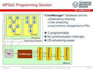
Simulator Generation Method of Configurable Processors for MPSoC. Yoshinori Takeuchi Osaka University. Background. Expansion of multi-functional portable multimedia devices requires high performance and low power processing

E N D
Simulator Generation Method of Configurable Processors for MPSoC Yoshinori Takeuchi Osaka University MPSoC 2009
Background • Expansion of multi-functional portable multimedia devices requires high performance and low power processing • MPSoC (Multi-Processor System-on-Chip) is a solution to achieve these requirements • MPSoC includes • Several processors • Several dedicated functional blocks • Communications on a chip MPSoC 2009
Problem of MPSoC design • Optimal MPSoC design • Repeated evaluation of SoC • Selection from a lot of processors, a lot of dedicated functional blocks and their communications • Exploration of MPSoC requires extremely long time • Multi or many-processors requires process partitioning • Processor design itself requires a large design time • MPSoC includes homogenous and heterogenous MP System • Bus or other components affects the performance MPSoC 2009
Solution for MPSoCevalution MPSoC 2009 • Combination of configurable processor (ASIP) developing environment and high abstraction level description enables efficient SoC simulation • Considering process partitioning when generating simulation model • Using configurable processor design environment • Using high level abstraction description on communications
ASIP1 Semaphore IO I/F Bus A Memory Special HW ASIP2 Bus B Architecture model of SoC Example of SoC • ASIPs, Buses, dedicated HWs • Dedicated HW • Memory, Semaphore • Communication between ASIPs • I/O Interface • Communication between input/output ports • Special HWs MPSoC 2009
MPSoC Evaluation Flow Process mapping to processors System specification SystemCdesc. of dedicated HW Processor specification ASIP design Bus modeling SystemC desc. of bus Software SystemCdesc. of ASIP Design Refinement Simulations MPSoC 2009 MPSoC 2009 6
Evaluation Flow 1/2 System Specification Process mapping ASIP specifications T1 ASIP1 ASIP2 T3 T2 T1 T4 T2 T4 SystemC desc. Of HWs Memory Dedicated HW T3 I/O I/F MPSoC 2009 MPSoC 2009
Evaluation Flow 2/2 Process mapping ASIP specifications Bus modeling ASIP1 ASIP1 ASIP2 T1 T4 I/O I/F T1 T4 T2 SystemC desc. Of HWs ASIP2 Memory Dedicated. HW Memory Dedicated HW T2 T3 T3 I/O I/F MPSoC 2009 MPSoC 2009
Evaluation and refinement Large Bus conflicts Bus partition Ex. Refinement • Evaluation Results • Bus occupations • Execution cycles • Examples of refinements • Bus collision • Bus partitioningsoftware refinement • Execution cycles • Process remapping • Instruction enhancement MPSoC 2009
Problem for MPSoC profiling information • MPSoC includes many ASIPs • ASIP achieves low HW cost, high performance, and low power using application specific instruction sets • Design of ASIP and its SW dev. Environment requires large man-month • Use of ASIP Design Environment reduces man-month • Input • Processor description • Output • Transaction Level Model of ASIP • Collects execution information • Software development environment Processor Description Soft. Dev. Environment ASIP MPSoC 2009
Target MPSoC Architecture ASIPs, special purpose modules, and connections • ASIP: Application Specific Instruction set Processor • Enhanced by specific instruction sets • Special purpose module • Communication and processing ex)Memory, IDCT • Connections • Arbitration between ASIP and modules • ex)Shared bus, crossbar switch • modeld in Transaction Level ASIP0 ASIP1 Shared bus IDCT Memory Ex. of MPSoC MPSoC 2009
Our approach Requirements for simulator Evaluation of total system High speed Accurate evaluation SystemC Enables System level design High level abstraction & cycle accurate simulation Propose SystemC based simulator generation from processor ADL description and Bus TL model Extension of HDL generator of ASIP Meister MPSoC 2009
Features of ASIP Meister • ASIP development environment • Quick Design Turn Around • GUI based Parameterized Design Entry • Behavior Description at Clock Cycle Level • Component DB (FHM: Flexible Hardware Model) • Automatic Generation of Application Program Development Tools • Compiler, Meta-Assembler Supplied • More Freedom • Design from Scratch • Design Modification from Pre-Designed Instances • Inherit Legacy Processor IPs MPSoC 2009
Configuration of ASIP Meister ArchitectureSpec. Architecture Design Entry (GUI) ApplicationProgram (C) Processor Synthesizer SW Development Tool Generator Compiler & Assembler SynthesisModel Gen SimulationModel Gen FHM-DBMS Module A ISS / HDL Simulator Object Code Behavior RT Report Logic Synthesis Area, Delay, Power, etc. Gate MPSoC 2009
Inputs of ASIP Meister MPSoC 2009 • Processor Description • Architecture Info. • Instruction length • Pipeline stage length • Used resources • Type of resource • Resource parameters • Instruction Set • Opcode and operand • Behavior of each stage • Interrupt • Issue condition and its behavior • Resource • Operation units and memory elements • From resource database • Information about resource • Operation type • Control signal value for operations • I/O Information
Structure of generated processor Top Level Controller Data Path Pipeline Ctrl. Signal Resource Ctrl.Sig MUX Resource State Machine Resource Pipeline Register Interrupt Ctrl. Signal Resource,MUX Ctrl.Sig Repeat stage # MPSoC 2009
SystemC generation flow Determine control signals and generate module definitions from processor description and resource database information Resource Database SystemC desc. of resources SystemC desc. Of ASIP Generation of SystemC desc. Processor desc. Ctrl. Signal information Definition of modules MPSoC 2009
SystemC generation from processor description (outline) 2. 1. A B A B C C D C D Inst.1 Inst.2 3〜5. Top Contoller Pipeline Ctl. Sig. A B Ctl.Sig State Machine Int. Ctl. Sig D C Ctl.Sig Analyze resource connections and ctrl signals each instruction Merge same resources Insert mux and pipeline registers Generate control signals Generate module definition according to types Generate SystemC MPSoC 2009
Module Definition andGenerated SystemC Description MPSoC 2009
SC_MODULE(module_name) { Ports and signals,Definition of submodules SC_CTOR(module_name) : Ports and signals,Initilization of submodules { Connections of submodules } Process definition }; 1.Generation of Class Definition • Input • Module name • Output • Definition of module type using SC_MODULE • Initialization using SC_CTOR MPSoC 2009
2.Generation of Port Definition3.Geneartion of Signal Definition // Definition sc_in< sc_uint<26> > sample; // Intialize sample("sample") Ex. of 26 bit input port • Bit width W determines type • W = 1 bool • 2 ≦ W ≦ 64 sc_uint<W> • 65 ≦ Wsc_biguint<W> • Input • Input/output port info. • signal • Generation • Definition of data type • Bit width data type • Simulation time largely depends on data type • Type and signal name • Initialization • Constructor with signal name MPSoC 2009
4.Generation of sub module definition // Declaration sub_module sub1; // Initialization sub1("sub1") // Connection sub1.dout(signal); Ex. sub_moduletypesub with port dout • Input • Info. of Submodule • Generation • Declarations • Type and instance name • Initializations • Constructor(instance_name) • Connections • Assign signal to each port MPSoC 2009
5.Generation of Process definition • Register type • Generated Process • Register update process • Signal assignment • Input • Signal assignments • Generated Process • Signal assignment processes • State machine type • Input • State transition table • Generated processes • State update process • State control process MPSoC 2009
Process Generation for State Update of State Machine State update process Initialization of reset State update at rising clock SystemC Description void change_state() { if( rst.read() == 1 ) { cur.write(ST_0); } else if ( clk.event() && clk.read() == 1 ) { cur.write( next.read() ); } } MPSoC 2009
Process Generation for Control State Transition of State Machine Input State Transition Table Generate following descriptions for each state T Judgement of current state Output signal State transition Condition of transition Next Transition State transition table State: ST_0 Output: out0 Condition: if (in=3)gotoST_1 ... SystemC description void manage_state { if(cur.read() == ST_0) { out.write(0); if(in.read() == 3) next.write(ST_1); } ... } MPSoC 2009
Process Generation for Register update Register Update process Initialize register on reset Output signal is updated at rising clock SystemC description void process() { if(rst.read() == 1) { dout.write(0); } else if (clk.event() && clk.read() == 1 ) { dout.write(din.read()); } } MPSoC 2009
Process Generation for signal assignment a[0] ← in0a(3,1) ← in1 b ← in0 c[0] ← in0 Signal assignments in process0 Signal assignments in process1 • Input & Output • Input: signal assignment statement • Output: Several processes • Point • Process # reduction • Generation • Goup assignments according to destination • Analyze input signals of each group • Make processes which have the same input signal MPSoC 2009
a[0] ← in0a(3,1) ← in1 b ← in0 c[0] ← in0 Examples of Process Generation for signal assignment Signal assignments in process0 Signal assignments in process1 Some assignments are combined for process reduction • SystemC description void process0() { sc_uint<5> tmp_a = a.read(); tmp_a[0] = in0.read(); tmp_a(3,1) = in1.read(); a.write(tmp_a); } void process1() { bool tmp_in0 = in0.read(); b.write(tmp_in0); sc_uint<3> tmp_c = c.read(); tmp_c[0] = tmp_in0; c.write(tmp_c); } MPSoC 2009
SystemC generation MPSoC 2009 • Extension of ASIP Meister HDL Generator • SystemC description is generated from processor specification • Buses and dedicated HWs are designed by designer • With profiling functions • For high speed simulation • Data type selection • Use data type which achieves high speed simulation • Reduction of the number of processes
Experiment 1: Confirm the behavior of SystemC description compared with behavior of VHDL description Target ASIPs Three ASIPS with different instruction sets and pipeline stages Simulator Modelsim: VHDL description OSCI Reference simulator: SystemC description MPSoC 2009
Evaluation of Generated SystemC Simulation time: 10^7 cycle instructions Objective: Speed check of generated SystemC MPSoC 2009
Experiment 2: • Objective • Design time overhead • Target ASIP • DLX_integer : 59 instructions, 5 stages, 1 delay slot • Brownie : 45 instructions, 4 stages, 0 delay slot • Brownie+added inst. : 46 instructions, 4 stages, 0 delay slot • Environment • Environment : CPU PentiumD 3.4GHz, Memory 2GB • Software : OSCI Reference Simulator on Fedora 8 MPSoC 2009
Target MPSoC Architectures Inst. Mem. Inst. Mem. IDCT ASIP0 Data Mem. ASIP0 Data Mem. Shared bus Shared bus Single Processor + IDCT Single Processor Inst. Mem.0 Inst. Mem.N ASIP0 Data Mem.0 ASIP N Data Mem.N ... Local bus0 Local bus N Global bus Shared Mem. Semaphore Multi Processors • Single Processor • Data Memory • Single Processor+IDCT • Multi Processors • ASIPs have Inst. &DataMemory • Communication:Shared Memory & Semaphore MPSoC 2009
Evaluation of description 92% Generated Description Processor Description New Design Adding instructions MPSoC 2009
Evaluation of amount of descriptions excluding processors MPSoC 2009
Evaluation of profiling overhead S=Single Pr., D = DLX_integer, B = Brownie, M = Multi Pr. MPSoC 2009
Conclusion MPSoC 2009 Simulator generation method based on configurable processor developing environment and transaction level model bus SystemC description is generated by extension of HDL generation of processor Simulator overhead is not so large