Download
1 / 17
170 likes | 271 Views
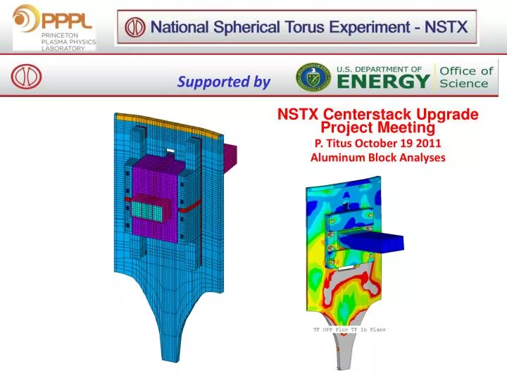
Supported by. NSTX Centerstack Upgrade Project Meeting P. Titus October 19 2011 Aluminum Block Analyses. TFInPlane=242058 TFInPlane=TFInPlane*.2248 TFInPlaney=-25516.9 TFInPlaney=tfinplaney*.2248 momy=254831 !N-M momy=momy*.2248*39.37 TFOOPForce=168311.2*.2248.

E N D
Supported by NSTX Centerstack Upgrade Project Meeting P. Titus October 19 2011 Aluminum Block Analyses
TFInPlane=242058 TFInPlane=TFInPlane*.2248 TFInPlaney=-25516.9 TFInPlaney=tfinplaney*.2248 momy=254831 !N-M momy=momy*.2248*39.37 TFOOPForce=168311.2*.2248 Load in Aluminum block (in coordinate system 200) coordinate system 200 (Cartesian) Titus Calc, EQ79 Ball End Struts, Welded Clevis z Han EQ 16 Ball End Struts, Welded Clevis Titus Calc, EQ 79 Spring Struts, Bolted Clevis Hand Calc **** SUMMATION OF TOTAL FORCES AND MOMENTS IN COORDINATE SYSTEM 5 NOTE: THE SUM IS DONE IN COORDINATE SYSTEM 5 FX = 139580.7 FY = 90927.03 FZ = 133837.8 MX = -1362.338 MY = 32135.61 MZ = 9598.212 SUMMATION POINT= 1.0624 2.4824 0.28466 x FX = -203828.1 N FY = -111829.7 N FZ = -17760.17 N MX = 169.0026 N-m MY = -5506.380 N-m MZ = -12044.77 N-m FX = 242058 N FY = 184800 N FZ = -25500 N MX = 0 N-m MY = 0 N-m MZ = 254831 N-m Vector Sum of FX and FZ 204,600N 193,377N 243,340N Mz at Alum Block 12044.77 N-m 9598 N-m 254831 N-m My at Alum Block 5506.38N-m 32135N-m 0 y x * this is 168*1.1 intended to apply the 10% headroom in PF current The 6 3/4 bolts should be preloaded to a minimum of 92 ft-lbs or 7375 lbs each to avoid cyclic loading. This produces a frictional restraint of 6*7373*.3 = 13275 lbs or 59052 N frictional restraint. Not enough to support the 184.8kN Top view
EQ79 1.09m *** SUMMATION OF TOTAL FORCES AND MOMENTS IN COORDINATE SYSTEM 5 NOTE: THE SUM IS DONE IN COORDINATE SYSTEM 5 FX = 139580.7 FY = 90927.03 FZ = 133837.8 MX = -1362.338 MY = 32135.61 MZ = 9598.212 SUMMATION POINT= 1.0624 2.4824 0.28466
Load Inventory from Inside the Umbrella Structure ~.5m 130kA*.5m*.5T = 195000N 130*3kA ~1T Average Field Across Leg=.5T
Bursting force from the inner TF components is the source of the radial finger loads. These are included in the loads from [1], [2]
Aluminum Block Tresca No Plasma With Plasma EQ #79
Can we get rid of this notch? CDR/PDR Analyzed to date Split Desired for Installation All the Block Clamp Bolts Pass Thru “Wing”
Mat 14 Mat 40 Mat 2 Mat 5 Mat 15 Mat 5 Mat 1 Mat 11 Mat 10
Gap Elements Used in the Model Gaps Between “Wing” and Umbrella Shell Gaps Under the Bolt Heads –Used for Preload Gaps Under the Bolt Heads –Used for Preload Gaps Between Block and Umbrella Shell Opening Gaps Between Block and Umbrella Shell Opening Gaps Between Block Flange and Umbrella Shell Gaps Between Block Flange and Umbrella Shell Gaps Under the Bolt Heads –Used for Preload
25ksi Bolt Preload Run ablk12 FEA simulates 3/8 Groove backed with a 3/8 Fillet Weld Allowable 14 ksi No PT 20 ksi with PT
25ksi Bolt Preload Preload Only Full Loading
Stress in psi Local Model EQ79 Global Model [2] EQ79 Stress in Pascal Bending allowable is 34.6 ksi. (25670 psi)
1.48 mm Vertical Displacement with respect to the block The differential motion in the theta Direction with respect to the block is .002727-.001207 = .001513. Global rotation needs to be subtracted –see below 0.5 mm Theta Displacement with respect to the block 1.87 mm Vertical Displacement with respect to the block In the global model the umbrella structure rotates .001207/1.0624 = .001136 rad and the global displacement difference just from the global rotation is 1.57/1.0624*.001207 =.00187m and the difference is .00187-.00127= .000606m or .6mm . The comparison is then 1.513-.6 = .9mm vs .5 mm for the local model.