Download
1 / 25
250 likes | 375 Views
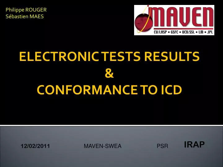
Philippe ROUGER Sébastien MAES. ELECTRONIC TESTS RESULTS & CONFORMANCE TO ICD. IRAP. 12/02/2011 MAVEN-SWEA PSR. CONTENTS. SWEA: Generalities Tests results & conformance to ICD A) Control voltage & HK Values stability B) Dynamic tests

E N D
Philippe ROUGER Sébastien MAES ELECTRONIC TESTS RESULTS&CONFORMANCE TO ICD IRAP 12/02/2011 MAVEN-SWEA PSR
SWEA PSR IRAP CONTENTS • SWEA: Generalities • Tests results & conformance to ICD A) Control voltage & HK Values stability B) Dynamic tests C) Notes III. PART STRESS ANALYSIS
SWEA PSR IRAP I. SWEA POTENTIALS Entrance grids HV_AN HV_MCP HV_DEF_UP V0 HV_DEF_DOWN GND Analyzer Deflectors MCPs
SWEA PSR IRAP I. SWEA POTENTIALS 16 anods Angular Azimut resolution: 22,5° Charge Amplifiers
SWEA PSR IRAP I. Electronic Boards
SWEA PSR IRAP I. Electronic Boards • 3 Boards: • HVPS_Board • High Voltage generation (2,2 kV) • 1.8kV for deflectors & 750V analyzer • 3,5 kV for MCPs • Voltage Scanning functions • HV COUPLING • Interface between high/low voltage functions • Collecting Anodes & Mechanical support for MCPs • Amplifier Board • Charge amplifiers (A111F)
SWEA PSR IRAP I. HVPS BOARD : Principle + + + + -12V +12V +28V HV_Analyzer 750V HV ANALYSER Cmd_Analyzer HK_Analyzer HV_Deflectors 1800V HV DEFLECTORS Cmd_Deflectors HK_Deflectors Cmd_V0 V0 Supply V0 (-25V) HK_V0 HV MCPs Cmd_MCP HV_MCP 3500V HK_MCP HVPS BOARD HK HV
SWEA PSR IRAP I. HVPS BOARD : Principle HV Transformer Deflector up Deflector Down Analyzer a) Deflectors & Analyzer voltages 1.8kV 2,2kV optocouplers Oscillator Voltage Multiplier Frequency: 100 kHZ Commands 750V
SWEA PSR IRAP I. HVPS BOARD : Principle HV 3.5 kV Transformer MCPs Oscillator Voltage Multiplier Feedback HK MCP Cmd MCP b) MCPs voltage Frequency: 100 kHZ
SWEA PSR IRAP II. Test Conditions • The thermal tests were performed at the following temperatures : -40°C, -10 °C, +20°C, +40°C, +60°C using a thermal chamber BIA TH6-25 in ISO8 clean room facility. • For planetary protection reasons, the thermal chamber was cleaned with sterile alcohol and heated at 150°C during 6 hours.
SWEA PSR IRAP II. SWEA Electrical Consumption
SWEA PSR IRAP II. A) CONTROL VOLTAGES Nominal Gain HV output (V) T1 Extrem curves on T°range Worst unstability (on T° range) T2 ICD Stability (%) Offset ICD Stability (V) CMD (V)
SWEA PSR IRAP II. A) CONTROL VOLTAGES: tests results
SWEA PSR IRAP II. A) CONTROL VOLTAGE: OFFSETS
SWEA PSR IRAP II. A) HK Values : test results
SWEA PSR IRAP II. B) HV DEF1,DEF2,ANAL dynamic response Overshoot HV max 95% Requirements : Settling time < 500 µs Overshoot < 1 % 0V rise time settling time
SWEA PSR IRAP II. B) HV DEF1,DEF2,ANAL dynamic response
SWEA PSR IRAP II. B) HV DEF1,DEF2,ANAL dynamic response (1) Overshoot not included because lower than 1% of HV max
SWEA PSR IRAP II. B) HV DEF1,DEF2,ANAL dynamic response NOTES The dynamic responses of the HV were tested in the worst case conditions (0V to max HV) small steps linear ramp Sweep Waveforms The dynamic of the HV depends on the dynamic of the command signal which might be different on the SWEA digital board
SWEA PSR IRAP II. C) NOTES • Temperature range of HVPS thermal tests is - 40°C to + 60°C which is wider than the expected temperature. • The tests results depend on the test conditions so some values (offsets, dynamic response) might be slightely different when the sensor will be connected to the digital board. • The main problem concerns low energy measurements because of the effect of offsets on low HV values. A calibration might be performed at SSL with digital board connected.
SWEA PSR IRAP III. Part Stress Analysis Summary
SWEA PSR IRAP III. Part Stress Analysis Summary
SWEA PSR IRAP III. Part Stress Analysis Summary
SWEA PSR IRAP III. Part Stress Analysis Summary NOTES
SWEA PSR IRAP THANKS FOR YOUR ATTENTION