Download
1 / 50
1.2k likes | 2.01k Views
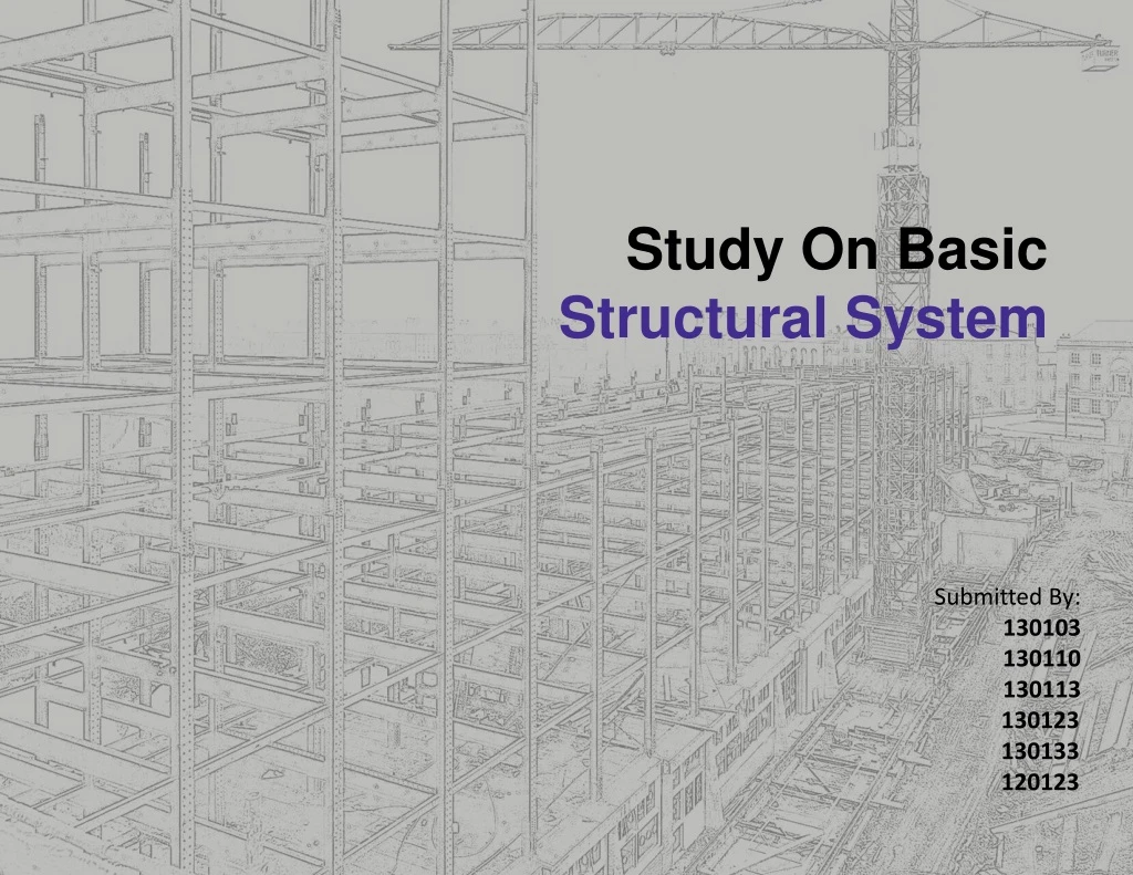
Study On Basic Structural System. Submitted By: 130103 130110 130113 130123 130133 120123. CONTENT. 03. GROUP. Introduction. Structure

E N D
Study On Basic Structural System Submitted By: 130103 130110 130113 130123 130133 120123
03 GROUP Introduction Structure Structure is a fundamental, tangible or intangible notion Construction or framework of identifiable elements (components, entities, factors, members, parts, steps, etc.) which gives form and stability, and resists stresses and strains. The basic frame work and skeleton provide for both erection and stability of any structure consist of two portion: 1. substructure 2. superstructure 01
03 GROUP The relationship of structure to building The simplest way of describing the function of structure is to say that it is the part of a building which resists the loads that are imposed on it. building may be regarded as simply an envelope which encloses and subdivides space in order to create a protected environment. The surfaces which form the envelope, that is the walls, the floors and the roof of the building, are subjected to various types of loads. external surfaces are exposed to the climatic loads. floors are subjected to the gravitational loads of the occupants and their effects Gravitational loads and the occupation of the building cause roof and floor structures to bend and induce compressive internal forces in walls. Wind causes pressure and suction loads to act on all external surfaces. 02
03 GROUP The relationship of structure to building A building structure must be able to support two types of load. 1. Static load. 2. Dynamic load. Static load: Assumed to be constant in nature. Its two type. 1.Dead load 2.Live load Dead load: Dead loads are relatively fixed and include the weight of the building structure itself as well as the weight of any permanent elements with in the building such as mechanical equipment. Live load: Live loads are moveable loads which may not be present all of the time . They include the weight of a building occupants and , furnishing as well as show loads no roof. Dynamic load: Can be applied to a structure suddenly and vary in magnitude and location. Dynamic load 03
03 GROUP Structural requirements • To perform its function of supporting a building in response to whatever loads may be applied to it, a structure must possess four properties: • it must be geometrically stable. • Geometric stability is the property which preserves the geometry of a structure and allows its elements to act together to resist load. The distinction between stability and equilibrium is illustrated by the framework • it must be capable of achieving a state of equilibrium. • This requires that the internal configuration of the structure together with the means by which it is connected to its foundations must be such that all applied loads are balanced exactly by reactions generated at its foundations. • it must have adequate strength. • The requirement for adequate strength is • satisfied by ensuring that the levels of stress • which occur in the various elements of a • structure, when the peak loads are applied, are • within acceptable limits. • it must have adequate rigidity. • Structural calculations allow the • and rigidity of structures to be controlled • precisely. They are preceded by an assessment • of the load which a structure will be required • to carry. 04
03 GROUP Structural Development in Architectural History • Time period: 6000 BC • Pre-Historic period: • Man came from cave for hunting. • Use of timber for building materials. • The structural system was post and lintel type. • Materials were clay, timber and stone. • Time period: (3000-2750) BC • Stone henge: • The massive stones that made up the monuments of stone henge. • Trabiated structural system. • Load is transferred from beam to column. • Accurate structural system is since unknown. Time period: (3200 BC 14 AD) Egyptian Architecture: Huge structure to show their power. Use of timber beam. Works of monolithic stone masonry. Columns made by single rock. The structural system was post lintel or post slab. Massive walls and lintels was supported by flat roof. Time period: (2371-325BC) Aesian Architecture: Stone was rarely used as building materials as it was not available. Sun dried or kiln burnt bricks were used as building materials. Use of timber as a column and logs as main roofing materials. Flat timber roof was used to cover a larger span and it allowed columns to be slander and graceful. 05
03 GROUP Time period: (1700-1380) Crete Architecture: Structural system was post lintel , it was mostly flat roof which were supported by walls constructed of stone blocks , rubbles and mud brick with reinforced. Time period: (1250-300)BC West Asiatic Architecture: Trabiated structural system. Columns were well ornamented. Time period: (600-30)BC Greek Architecture: Stone was the main construction materials Trabiated structural system. Stablishment of post lintel system. Columns were used in Greek pattern. Columns are set as vertical supporting element of the main structure. Acropolis: Great example of Greek Architecture. 06
03 GROUP Time period: (300BC-365AD) Roman Architecture: The Architecture was that of Greek but they developed the post and lintel system. Structural system was post slab and post lintel. Post lintel system developed as column are used in circular and rectangular way. Stability of Structure was easily ensured. Time period: (313-800AD) Early christian: Handmaid rubble, concrete brick or stone were main building materials. Construction system was archuated and trabeated. Time period: (330-1453AD) Byzantine architecture: Construction material was limestone and sand mortar. Construction system was wall slab. 07
03 GROUP Time period: (12th-16th century) Gothic architecture: Structural system was mainly post-lintel. Use of tall structure. Time period: (14th-17th century) Renaissance architecture: Symmetrical arrangement in free standing wall and support. The wall thickness was lessened. It diminished equally from the center. 01 08
03 GROUP Basic structural elements Walls- Load Bearing: Structural walls are the vertical constructions of a building that enclose a building. Structuralwalls may also be internal partitions used for load-bearing conditions forming part of thestructural framing system. There are two types of load bearing slab. MAIN BAR DISTRIBUTION BAR Slabs:Slabs generally refer to various types of floor systems designed to support floor and sometimes roofloads. slab One Way Slab Two Way Slab Waffle Slab Load bearing wall 09
03 GROUP Beam: Beams are typically horizontal structural members designed to carry a load. Steel is one of themost common materials used for beams, since it can withstand very heavy loads. Column: Are upright vertical structural members that supportslabs, beams or trusses 10
03 GROUP Analysis of Structural system: In strictly technical terms , structure may be considered as the means of translating external force into internal loads caring mechanism in order to support and reinforce an Architectural concept. There are basic three types of structural system . 3.Post slab structural system. 1.Wall slab structural system. Slab 2.Post-lintel structural system 11
03 GROUP WALL SLAB STRUCTURAL SYSTEM WALL SLAB Continuous or linear support system to transfer the external loads to the ground with the help of wall and slab.A load bearing wall is a wall that bears a load resting upon it by conducting its weight to a foundation structure. • Structural Member • Wall ( vertical load bearing member ) • Cellular wall arrangement : Load bearing wall Non load bearing wall Vertical load bearing member The structure consists of walls each joined to its neighbor. The external walls form the boundaries of the building and the internal walls divide the building into cells (rooms) making the building cellular. 12
03 GROUP • Double cross wall structure: • Simple cross wall structure • Complex wall arrangement If the rooms are to have effective day-lighting it will be observed that there is a limit to the depth of building which can be constructed on more complex system of cross walls set parallel to both major axes of the building. Load bearing wall Non load bearing wall This type of structure is suitable for a hostel or hotel building having a large number of identical rooms. All kind of hybrids between cellular and cross-wall arrangements are included under the heading complex wall arrangement 13
03 GROUP Slab ( horizontal load bearing member ) Slab • One way slab • Two way slab • Waffle Length / width >=2 …one way slab Length / width <=2…two way slab For Large Span waffle slab constructed 14
03 GROUP • Opening • Not more than 30% of the load bearing wall • Continuous horizontal opening avoided • Arch framework or lintel is used • Opening can be made from floor to wall • Small opening • Opening is of trabeated or arcuate system Live load & dead load Slab Wall Footing Ground First Unitarian church: Kahn Massagno; Mario Botta Load transfer method • Load transferring system towards ground through wall • Load of the dome transfers with circular planned wall according to its periphery. • Dome supported on squinches . 15
03 GROUP • Position of stair • Landing should be supported by load bearing wall • The wall in both sides is the main structural member Stair case 06 06 • Parallel walls on two sides can also provide support. • Arch also can provide support for stair. Theatre and Cultural Centre in Chambery; Mario Botta • Span • 12’-15’ • Large span of roof Is problem and it may be solved by waffle slab • One way slab casting : L=1.5W Waffle 16
03 GROUP • Punch making method • Generally punch can not be possible. • Only a punch is appeared on first floor with respect to four walls around it. • Punch can not be done 1/3 of the area of the roof 35’ 4” 12” Parekh house • Cantilever • Generally on cantilever is used 35’ • Material • Reinforced concrete slab with wooden , brick, stone wall • Wall position/wall thickness • Primarily 12”at six storey level and increases 4” at every one storey down • For buildings not more than 3 stories or 35’ in height, masonry walls may be 12” thick • One stored solid masonry walls not more than 9’ high may be 10” thick. • Positions of walls are same. Private house in Losone ; Mario Botta 17
03 GROUP • Height • Generally 6 storied • Cost and time • Low rise building –this system represents economy • Generally low cost construction • Foundation –more shallow than other system • Construction period –larger than any other system Twin house, Charles Correa • Formal Expression • Plan –no grid pattern, can be any desired shape • Large ,unbroken plans could be expressed • In elevation – small punches • For large openings ,arches are provided • Massive and bold • Arch, dome, and vaults can be constructed in this type of structure • Cantilevers can expressed as planes • Solid void relation is boldly represented • For hot dry climate this type of structure gives extra benefit. • Screen wall can be added • This type of structure lasted for thousand years. Bangladesh Eye Hospital , Louis I Kahn First Unitarian Church , Louis I Kahn 18
03 GROUP Case study : 1 Cymbalista Synagogue ; Mario Botta Plan- No grid pattern Section- clear referencing of load bearing wall Elevation- clear expression of wall slab structure in opening Opening- small openings Plan Top view Section Elevation 19
03 GROUP Case study : 2 Church of Santo Volto ; Mario Botta 06 Brick wall is used which carries the load. No expression continuous opening. Solid void relationship is in pleasing condition No grid pattern in plan Vertical linear opening No cantilever space. 20
03 GROUP Wall slab structural system Strength Weakness • For low storied structures this system is economical. • Foundation is shallower than other systems, so foundation cost is the least of all. • This type of construction lasted for thousands of years. The construction of Mohenjo-Daro built about 2500 B.C can be still identified • Arches, Domes and Vaults are used in this system. • Post does not disturb the free space. • Span of the area is not enough. Maximum 12’. • Limitation of structure height 6-7 storied. • Walls must be built over a wall. • More time is required • Small space over a big space is not possible. • Continuous opening can not possible Opportunity Threat • Screen wall can be used. • Natural color can be obtained in the building surface, by different exposed brick of different hue. • For hot dry climate this type of structure gives extra benefit. • Wall thickness sometimes is extra beneficial for shading. • This system could expresses the composition of Horizontal and vertical plane. • This type of construction is not possible with out good load bearing capacity of earth. • Flexibility of massing is very small floors can taper & up-ward. • Dampness is also greater problem. 21
03 GROUP Post lintel In Architecture post and lintel structural system is a simple construction technique also called column and beam, horizontal member is supported by two vertical posts at either end. All structural opening have evolved from this. Post-and-beam structures are either loadbearing wall structures or frame structures. A large range of spans is also possible depending on the types of element which are used. BEAMS COLUMN Parthenon, GREEK 22
03 GROUP LOAD BEARING SYSTEM OF POST LINTEL Load Dead load and Live load Lintel Columns Footings Ground Single square grid Multiple square grid Multiple rectangular grid Single rectangular grid 23
03 GROUP Two way slab One way slab If Length = L Width = W, & L/W > 2 Then the slab works as a one way slab Orientation of members For Beam RECTANGULAR PLAN RADIAL GRID For Column 24
L/4 L/4 L/2 03 GROUP Span An overhang where one floor extends beyond and over a foundation wall. Can be possible even more than 30-50%(economic) Span is limited,17’-22’ is economical. Beam is proportional to span of slab. Such as span40’ than the width40’’. Punch possible possible Not possible Punched on the slab can be obtained without any disturbance. 25
03 GROUP Wall Wall must be placed over a beam. As wall does not carry any load opening can be created anywhere of the wall,100% opening in wall surface is possible. Stair Stair must start with respect to a beam 26
03 GROUP • Expression: • Post and lintel are shown as a frame work. • Beam can be shown under or over the roof as inverted beam. • Column and beam can be identified. • Columns are placed along the edge line of the building. • Building height increase for the beam to get clear space. • Unexpected lines can be formed in elevation. • Unexpected beam can disturb the indoor spatial qualities. Time and cost: Time period less than wall slab system. More costly than wall slab(30% more for low rise than wall slab). Economical for large span building Context: Suitable for composite climate Material: R.C.C, iron, brick, timber, stone, steel 27
03 GROUP South 5053 Apartments Designed by -shatotto 28
03 GROUP HMC Architects designed the Willow Elementary School, in the Los Angeles 29
03 GROUP • Advantage • Maximum column to column opening can be provided easily • Roof can be provided flat, pitch or any other shape • Punch in slab can be provided easily • Aesthetic framework can be done • Disadvantage: • The biggest disadvantage to a post and lintel construction is the limited weight that can be held up, and the small distances required between the posts. • The tension induced by deformation of self-weight and the load above between the posts. 30
03 GROUP Post Lintel Structure System Weakness Strength • Unexpected beam hampers interior. • Acoustic problem may occur. • Stairs must be started with the reference of beam • 50% cantilever system is applicable. Opportunity Threat • : • Maximum column to column opening • Any type of roof can be provided • Aesthetic framework can be done • If beam is not strong enough, where large span, huge concentrated load may occur bending stress and deflection. • Short span beams with large concentrated load near the posts will occur shear stress . 31
flat plate post slab flat slab with drop flat slab with capital & drop 03 GROUP • Post slab structural system: • Members: Column , Slab • Slab_ Horizontal structural member • Post_ Vertical structural member • Classification of post slab: • flat plateB. flat slab : with capital with drop with capital & drop flat slab with capital 32
L Column strip Middle strip slab post G.L. footing 03 GROUP Materials: R . C . C , iron Load transfer system: The load of the slab it self and other live load transfer to the post by the slab. both the dead load and live load which the post gets form the slab transfer to the ground by the post. Load ▻ slab ▻ column ▻ ground 33
03 GROUP Span: effective span horizontal distance between center points of two vertical support. clear span horizontal distance between internal faces of two vertical support. Ecomonical17’-22’ effective span clear span Cantilever:Floor slab in all across must be cantilevered and it will be 1/3 of the span of the postmaximum cantilever will be 33- 50% of the span. Position of wall: Wall can be built freely as desired in different floors. it is recommended to built walls on the column strips. It is better to avoid the middle strips from first floor. 34
03 GROUP Stair position: Stair can be created from middle strip. Simply supported stair. Stair can be created by using cantilever as landing. Maison Citrohan Le Corbusier Opening: Any kinds of opening of any size can be provided Ribbon window –possible Cottbus university library Villa Stein-De-Monzie Le Corbusier Villa savoye; le corbusier 35
03 GROUP Punch in slab: in the area common to the slab middle strips. in the area common to two column strips, not more than one-eighth the width of the strip in either span should be interrupted by openings.. in the area common to one column strip and one middle strip, not more than one –fourth of the re-enforcement in either strip should be interrupted by the opening. Maison Citrohan Le Corbusier 36
03 GROUP Position of wall: Wall can be built freely as desired in different floors. it is recommended to built walls on the column strips It is better to avoid the middle strips from first floor 06 Johnson Wax Administration Building Frank Loyd Wright MRF Headquarter Charles Correa 37
03 GROUP Expression: The plan of the building of post and slab system is regular shaped and respect strong square grid pattern. The slab is always cantilevered from the post. Solid void relationship is strongly achieved Vertical reference is maintained 38
03 GROUP Expression: Massing constructed in post and slab system has an effect of floating Continuous opening can be provided Advantage: Ribbon window or large opening is a greater opportunity Cantilever 33%_50% possible Slabs can be cut as freely as needed Position of enclosing wall can be changed in different floor plan Different types of shading device can be used Partition wall can be use as required 39
03 GROUP CASE STUDY: 06 Villa savoya Le corbusier 40
03 GROUP Load transfer system: slab/floor Column Footing subsoil 41
03 GROUP Orientation: Square grid pattern 42
03 GROUP Cantilever: Opening: Continuous opening, ribbon window 43
03 GROUP Punch in slab: Large Punch, without disturbance of beam 44
03 GROUP Stair in the middle strip “.......From structural view point punches in the slabs are best located well away from the columns, preferably in the area common to the slab middle strip. Unfortunately architectural consideration usually cause them to be located close to the columns.” Expression: • Ground floor a band of column, and in the first floor strip of ribbon window. • The main body of the house is limited by four similar walls. • Solid void relationship found here. • Floating effect 45
03 GROUP Post slab structural system Strength Weakness • Economical for low storied structure • Shallow Foundation • Long lasting • Continuous ribbon window for panoramic view is impossible. • Wall thickness is greater than in the other two systems. • As for the poor opening ratio, it is not suitable for our climatic condition. • Small space over a big space is not possible. • Wall must be built over a wall. Opportunity Threat • Plans follow no grid pattern; it can be of any desired shape. • Large, unbroken plans could be formed. • Extra benefit for hot dry climate • Wall thickness sometimes extra beneficial for shading. • Post does not disturb the free space. • Not usually suitable for high-rise • Span of the area is not large enough. • Allowable amount of cantilever is limited • Low Flexibility of massing 46
03 GROUP COMMON FEATURE 47
03 GROUP Reference A Visual Dictionary of Architecture, Francis D.K. Ching Building construction illustrated, Francis D.K. Ching Complete works of Tadao Ando BUILDING CONSTRUCTION ILLUSTRATED,FRANCIS D. K. CHING VISUAL DICTIONARY OF ARCHITECTURE, D.K CHING Design of concrete structure 14 PHILOPHY AND DESIGN FROM ENGINEERING TO ARCHITECTURE DESIGN OF MASONARY STRUCTURE , A.W. HENDRY, B. P. SHINHA,S. R. DEVIS DESIGN BASED PLLANING FOR COMMUNITIES STHAPOTTO O NIRMAN ARCHITECTURAL MONOGRAPHS –MIES VEN DER ROHE 48