Download
1 / 30
300 likes | 328 Views
Explore the development of superconducting coils for various applications like MRI models, undulators, and solenoids. Detailed testing and instrumentation processes ensure high performance and reliability.

E N D
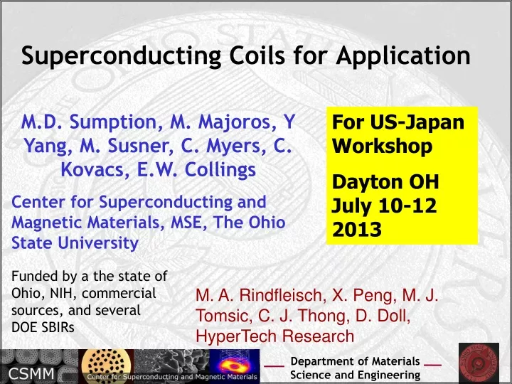
Superconducting Coils for Application M.D. Sumption, M. Majoros, Y Yang, M. Susner, C. Myers, C. Kovacs, E.W. Collings Center for Superconducting and Magnetic Materials, MSE, The Ohio State University For US-Japan Workshop Dayton OH July 10-12 2013 Funded by a the state of Ohio, NIH, commercial sources, and several DOE SBIRs M. A. Rindfleisch, X. Peng, M. J. Tomsic, C. J. Thong, D. Doll, HyperTech Research
B z-axis SuTC-Magnets Small Scale Model Undulator for International Linear Collider Rotor coil for NASA MgB2 small scale MRI model (left) and solenoid coil (right) Coil Winding: HTR Coil Instrument and Test- OSU
Selected Previous Coils Also series of small YBCO coils – Ic, thermal Propagation and NZP • Small Solenoids, MgB2 (to 850 m of wire) • Small Racetracks, MgB2 • Rotor Coil, MgB2 • Wind and React “segmented coil” seg • Undulator Coil, MgB2 • Solenoid and Undulator Coil Nb3Sn
Outline of Present Work • Small 15 K Coil, MgB2 • E-lenz Coil, HTR, BNL • Model Helical and Planar Undulators – Nb3Sn • Wire-In-channel Development and NZP Estimation – MgB2 • 100 m length of MgB2 instrumented (MRI-like Coil Winding, but one layer) for Thermal, Ic, and NZP measurement
Helical Undulator – ILC-like Majoros On-Axis field = 0.8 T
Pushing for higher freq. in ILC-like Helical Undulators • Pushing to 11 -12 mm requires 1 T • Pushing to 10 mm requires 1.07 T (Assuming K = 1)
Needs for Planar Undulators Conductor: Nb3Sn tube-type 192 filament strand, 0.5 mm OD (not insulated), 0.65 mm OD (insulated) Winding cross-section:, winding size 4.8 mm x 5.458 mm, 9 layers, number of turns = 60 Je=2950 A/mm2, 4.7 T
Results: Planar Undulator segment • At maximum quench current of 357.3 A obtained experimentally, the corresponding maximum on-axis field is 1.6 T.
WIC and Coil Test • WIC Test • Coil Manufacture and Test
WIC NZP and Quench (gas cool) NZP: 0.5-1 cm/s
MgB2 Coil, 100 m of WIC MgB2 Conductor HTR: MgB2 strand, Wire-in-channel Conductor HTR: Coil wound, coil epoxy impregnated by HTR OSU: Coil Instrumented with 30+ voltage taps, 18+ thermocouples, , other sensors OSU: Cool down and Test
Cu-Stabilized YBCO Extensions to BSCCO-Leads Rough Schematic Current-Tap 1 (CT1) Current-Tap 2 (CT2) Winding Height= 92mm Single Layer, 34-Turn (~100m) WIC MgB2 Coil
Instrumentation V-tap wires: (MWS) 30HPN-155, insulated copper wire. Thermocouples: (Omega) 5LRTC-KK-E-24-48, Type-E. Heaters: (Birk) BK3542, Kapton-insulated Nichrome heater. The heater active areas were double the width of the WIC so they were folded over. V-Tap wires run along coil turns, then twisted off as V-tap pair to minimize inductive signal
V1 V2/V3 V4/V5 V6/V7 V8/V9 V10/V11 V12/V13 V14/V15 V16/V17 V18/V19 V20/V21 V22 T1 T2 T3 T4 T6 T7 T8 T9 T5 T10 T11 Ic Homogeniety Instrumentation: V-taps CT1 CT2 Note: V1 & V2 are a voltage tap pair (shown by twisted wires). V2/V3 only refers to the fact that both of these wires are soldered to the sample at the same location
V1 V2/V3 V4/V5 V6/V7 V8/V9 V10/V11 V12/V13 V14/V15 V16/V17 V18/V19 V20/V21 V22 T1 T2 T3 T4 T6 T7 T8 T9 T5 T10 T11 TC-bead (uninsulated) Gently scraped away WIC insulation GE-varnish and thin cigarette paper insulation (1.27 μm thick) Ic Homogeniety Instrumentation: Temp CT1 CT2
V1 V2/V3 V4/V5 V6/V7 V8/V9 V10/V11 V12/V13 V14/V15 V16/V17 V18/V19 V20/V21 V22 T1 T2 T3 T4 T6 T7 T8 T9 T5 T10 T11 A1 A2 A5 A6 T13 T25 V23 H1 V24/25 V26/27 V28/29 V30/31 V32/33 V34/35 V36/37 V38/39 V40/41 V42/43 H2 V44 T12 T15 T16 T17 T18 T19 T20 T21 T22 T23 T24 A3 A4 A7 A8 T14 T26 NZP Instrumentation: V-taps, T, Heaters CT1 CT2 Located between V11 &V12 CT1 CT2 A1-8 V-taps & T13,14,25,26 TCs are on the nearest neighbor turns to witness possibility of transverse NZP V23 is 47.272 meters from the edge of CT1 going towards the winding
A1 A2 A5 A6 T13 T25 V23 H1 V24/25 V26/27 V28/29 V30/31 V32/33 V34/35 V36/37 V38/39 V40/41 V42/43 H2 V44 Making Kapton-insulated nichrome heater correct width T12 T15 T16 T17 T18 T19 T20 T21 T22 T23 T24 6mm 6mm A3 A4 = Active Area A7 A8 T14 Folded in half T26 6mm 3mm NZP Instrumentation: Heaters V23 is 47.272 meters from the edge of CT1 going towards the winding CT1 CT2 Note: the closest distance of the active areas of the heaters H1 to H2 is 36.8cm. The “true” active width (the nichrome wire) was 4.49mm and ~2.3mm after folding
A1 A2 A5 A6 T13 T25 V23 H1 V24/25 V26/27 V28/29 V30/31 V32/33 V34/35 V36/37 V38/39 V40/41 V42/43 H2 V44 T12 T15 T16 T17 T18 T19 T20 T21 T22 T23 T24 A3 A4 A7 A8 T14 T26 V23 is 47.272 meters from the edge of CT1 going towards the winding NZP Instrumentation:V-taps CT1 CT2 Note: V23 & V24 are a voltage tap pair (shown by twisted wires). V24/25 only refers to the fact that both of these wires are soldered to the sample at the same location Note: A1-8 voltage taps are shown in another NZP instrumentation diagram
A1 A2 A5 A6 T13 T25 V23 H1 V24/25 V26/27 V28/29 V30/31 V32/33 V34/35 V36/37 V38/39 V40/41 V42/43 H2 V44 TC-bead (uninsulated) T12 T15 T16 T17 T18 T19 T20 T21 T22 T23 T24 A3 A4 A7 A8 T14 T26 Gently scraped away WIC insulation GE-varnish and thin cigarette paper insulation (1.27 μm thick) NZP Instrumentation: Thermocouples CT1 CT2 Note: T13,14,25,26 thermocouples are shown in another NZP instrumentation diagram
A1 A2 A5 A6 T13 T25 V23 H1 V24/25 V26/27 V28/29 V30/31 V32/33 V34/35 V36/37 V38/39 V40/41 V42/43 H2 V44 T12 T15 T16 T17 T18 T19 T20 T21 T22 T23 T24 A3 A4 A7 A8 T14 T26 NZP Instrumentation: Neighboring Strands CT1 CT2 Transverse distance of the neighboring taps/TCs to the center of the main strand is ~2.4mm
Inside of OSU Dewar OSU Constructed YBCO Busbar
Tc transition for coil Tc = 39 K
OSU Coil Test Bed – Test of Coil • Cryocooled Test Bed capable of cooling coil 4’ OD by 2’ high to 4 K • Two Sumitomo Cryocoolers • 700 A Current lead DC • Labview controlled DC or AC • Coil being tested with active protection circuits on 10 segments • Possible to use voltage control 63 KVA PS Cryostat 2ft x 4 ft Coil Xfrm (2 kA) Test Bed
Summary • Coils of various kinds have been made, including Solenoids, pancakes, segmented coils, model helical undulators, Fault current limiting coils, Model coil set for planar undulators, rotor coils, and others • Coils have been made with MgB2, YBCO, Nb3Sn • Coils are bring developed for operation at 4 K, higher temperature, liquid helium, cryocooled, and intended for 20 K helium waste gas cooling • A wire in channel has been developed, and quench properties have been evaluated • A coil has been wound with this WIC, and is being tested presently