Download
1 / 18
190 likes | 344 Views
Mobility Management with Multi-Carrier Support for IEEE 802.16m. Document Number: C802.16m-08/564 Date Submitted: 2008-07-07 Source: Kelvin Chou Kelvin.Chou@mediatek.com Yih-Shen Chen Yihshen.Chen@mediatek.com I-Kang Fu IK.Fu@mediatek.com Paul Cheng Paul.Cheng@mediatek.com

E N D
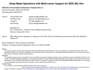
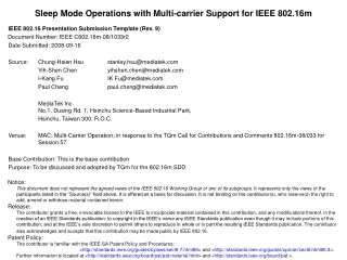
Mobility Management with Multi-Carrier Support for IEEE 802.16m Document Number: C802.16m-08/564 Date Submitted: 2008-07-07 Source: Kelvin Chou Kelvin.Chou@mediatek.com Yih-Shen Chen Yihshen.Chen@mediatek.com I-Kang Fu IK.Fu@mediatek.com Paul Cheng Paul.Cheng@mediatek.com MediaTek Inc. No.1, Dusing Rd. 1, Hsinchu Science-Based Industrial Park, Hsinchu, Taiwan 300, R.O.C. Venue: IEEE 802.16m-08/024 “Call for Comments and Contributions on Project 802.16mSystem Description Document (SDD)” In response to the topic: Upper MAC concepts and methods (mobility management) Base Contribution: N/A Purpose: To be discussed and adopted by TGm for the 802.16m SDD
Outline • Multi-Carrier Mobility Management Design Concept • Scanning with Multi-Carrier Support • Intra-Frequency Handover • Inter-Frequency Handover • SDD Text Proposal
Multi-Carrier Mobility Management Design Concept • The MS may maintain its normal operations with the serving BS on one carrier (using one RF) while perform scanning or network re-entry to the target BS on another carrier (by another RF)
Scanning in Multi-Carrier System • In cell reselection, the MS scans primary (fully-configured) carriers of neighbor BSs • The MS may also scan other primary carriers of its serving BS
Scanning with Multi-Carrier Support (1/4) • Scanning using the RF other than the one for its primary carrier • The MS dedicates its secondary RF for either normal scanning or autonomous scanning • In normal scanning, the scanning request/response messages can be exchanged over either the primary carrier or the secondary carrier • Scanning operations go in parallel with normal operations on the primary carrier
Scanning with Multi-Carrier Support (2/4) • An example of the MSC for scanning using secondary RF • RF #2 is dedicated to scanning • Scanning request/response can be exchanged via either carrier #1 or carrier #2
Scanning with Multi-Carrier Support (3/4) • Scanning using multiple RFs simultaneously • Perform DL channel evaluation and synchronization to multiple frequency bands via multiple RFs simultaneously • To expedite the scanning operation (e.g. fast cell reselection)
Scanning with Multi-Carrier Support (4/4) • An example of the MSC for scanning using multiple RFs simultaneously
Intra-Frequency Handover (1/5) • Handover Scheme #1 • RF #1: primary carrier with S-BS until T-BS DL synchronization is done • RF #2: DL synchronization (and initial ranging if possible) with T-BS • Description • The MS may use another RF (e.g. RF #2) to acquire the DL/UL channel parameters of the target BS (e.g. timing/frequency offset ) before disconnecting its primary carrier (e.g. on RF #1) from the serving BS • After the DL/UL channel parameters are obtained, RF #2 may proceed to network reentry to the target BS, or it can pass the parameters to RF #1 to complete network reentry • Advantage • Reduced handover interruption time
Intra-Frequency Handover (2/5) • Handover Scheme #1 - Scenario 1 • The MS synchronizes with the target carrier (the primary carrier to handover to) of the target BS before disconnecting from the serving BS • The MS maintains its primary carrier with the S-BS (e.g. using RF #1) and uses another RF (e.g. RF #2) to synchronize to the DL channel on the primary carrier of the T-BS and acquire the DL/UL parameters • Remaining network reentry procedures (including initial ranging) are completed using RF #2 after the primary carrier to the S-BS has been disconnected
Intra-Frequency Handover (3/5) • Handover Scheme #1 - Scenario 2 • The MS synchronizes with a fully-configured carrier of the target BS other than the target carrier before disconnecting from the serving BS • The MS maintains its primary carrier with the S-BS (e.g. using RF #1) and uses another RF (e.g. RF #2) to perform initial ranging to a fully-configured carrier of the T-BS other than the target carrier • Remaining network reentry procedures are completed using RF #1 after disconnecting from the S-BS • The ranging parameters acquired by RF #2 (UL timing, power, etc.) are used by RF #1 to expedite its network reentry process
Intra-Frequency Handover (4/5) • Handover Scheme #2 • RF #1: • Primary carrier with S-BS until new primary carrier with the T-BS is established • Scheduled sleeping intervals • RF #2: network reentry to the T-BS within sleeping intervals • Description • The MS puts its primary carrier (e.g. carrier #1) into sleep mode and uses another carrier (e.g. carrier #2) for network reentry to the target BS within the sleeping intervals of its primary carrier • The primary carrier to the serving BS maintains connected until the new primary carrier to the target BS is established • Advantage • Make-before-break HO
Intra-Frequency Handover (5/5) • An example of the MSC for HO scheme #2 • Primary carrier goes sleep upon receiving Fast Ranging IE • RF #2 sends RNG_REQ within the sleep interval of the primary carrier
Inter-Frequency Handover (1/3) • Handover Scheme #1 can also be used for inter-frequency handover • RF #1: primary carrier with S-BS until initial ranging to the T-BS is done • RF #2: initial ranging to the T-BS • Description • The MS synchronizes with the target carrier of the target BS before disconnecting from the serving BS • The MS maintains its primary carrier with the S-BS (e.g. using RF #1) and uses another RF (e.g. RF #2) to perform initial ranging to the primary carrier of the T-BS • Remaining network reentry procedures (including initial ranging) are completed using RF #2 after the primary carrier to the S-BS has been disconnected • Advantage • Handover interruption time is reduced
Inter-Frequency Handover (2/3) • Handover Scheme #3 • RF #1: primary carrier with S-BS until new primary carrier with T-BS is established • RF #2: network reentry to the T-BS • Description • Using the secondary RF (any RF other than the one for the primary carrier) for network reentry • The primary carrier to the serving BS maintains connected until the new primary carrier to the target BS is established • New primary carrier is established on the secondary RF • Advantage • Make-before-break HO
Inter-Frequency Handover (3/3) An example of the MSC for HO scheme #3
Summary of Multi-Carrier Handover Schemes • Handover Scheme #1 • Intra-frequency handover • Inter-frequency handover • Handover Scheme #2 • Intra-frequency handover • Inter-frequency handover • Make-before-break handover • Handover Scheme #3 • Inter-frequency handover • Make-before-break handover
SDD Text Proposal • Add the following text into Session 10 of the SDD (IEEE 802.16m-08/003) • ----------------------- text begin ----------------------------------------------------------------------------- • 10.x Data/Control plane • 10.x.y MAC Handover Procedures • 10.x.y.z Handover with Multi-Carrier Support • The MS may use a secondary RF (any RF other than the one for the primary carrier with its serving BS) to perform full or part of the handover procedures. In this case, multiple RFs can be used cooperatively to reduce the handover interruption time or to achieve make-before-break handover. • ----------------------- text end -------------------------------------------------------------------------------