Download
1 / 38
440 likes | 751 Views
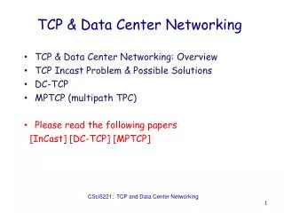
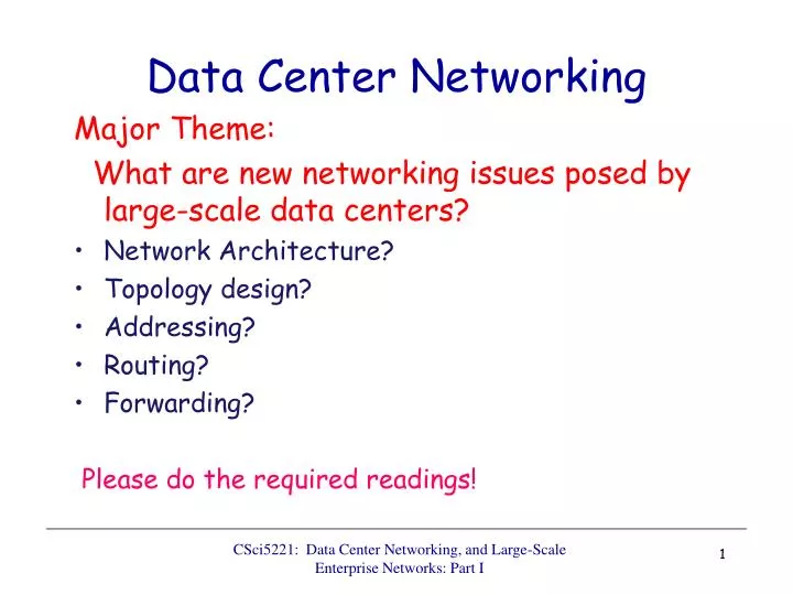
Data Center Networking. Major Theme: What are new networking issues posed by large-scale data centers? Network Architecture? Topology design? Addressing? Routing? Forwarding? Please do the required readings!. Data Center Interconnection Structure.

E N D
Data Center Networking Major Theme: What are new networking issues posed by large-scale data centers? • Network Architecture? • Topology design? • Addressing? • Routing? • Forwarding? Please do the required readings! CSci5221: Data Center Networking, and Large-Scale Enterprise Networks: Part I
Data Center Interconnection Structure • Nodes in the system: racks of servers • How are the nodes (racks) inter-connected? • Typically a hierarchical inter-connection structure • Today’s typical data center structure Cisco recommended data center structure: starting from the bottom level • rack switches • 1-2 layers of (layer-2) aggregation switches • access routers • core routers • Is such an architecture good enough?
Cisco Recommended DC Structure: Illustration Internet Internet CR CR Data Center Layer 3 … AR AR AR AR Layer 2 LB LB S S • Key: • CR = L3 Core Router • AR = L3 Access Router • S = L2 Switch • LB = Load Balancer • A = Rack of 20 servers • with Top of Rack switch … S S S S … … A A A A A A
Data Center Design Requirements • Data centers typically run two types of applications • outward facing (e.g., serving web pages to users) • internal computations (e.g., MapReduce for web indexing) • Workloads often unpredictable: • Multiple services run concurrently within a DC • Demand for new services may spike unexpected • Spike of demands for new services mean success! • But this is when success spells trouble (if not prepared)! • Failures of servers are the norm • Recall that GFS, MapReduce, etc., resort to dynamic re-assignment of chunkservers, jobs/tasks (worker servers) to deal with failures; data is often replicated across racks, … • “Traffic matrix” between servers are constantly changing
Data Center Costs • Total cost varies • upwards of $1/4 B for mega data center • server costs dominate • network costs significant • Long provisioning timescales: • new servers purchased quarterly at best • *3 yr amortization for servers, 15 yr for infrastructure; 5% cost of money Source: the Cost of a Cloud: Research Problems in Data Center Networks. SigcommCCR 2009. Greenberg, Hamilton, Maltz, Patel.
Overall Data Center Design Goal Agility – Any service, Any Server • Turn the servers into a single large fungible pool • Let services “breathe” : dynamically expand and contract their footprint as needed • We already see how this is done in terms of Google’s GFS, BigTable, MapReduce • Benefits • Increase service developer productivity • Lower cost • Achieve high performance and reliability These are the three motivators for most data center infrastructure projects!
Achieving Agility … • Workload Management • means for rapidly installing a service’s code on a server • dynamical cluster scheduling and server assignment • E.g., MapReduce, Bigtable, … • virtual machines, disk images • Storage Management • means for a server to access persistent data • distributed file systems (e.g., GFS) • Network Management • Means for communicating with other servers, regardless of where they are in the data center • Achieve high performance and reliability
Networking Objectives • Uniform high capacity • Capacity between servers limited only by their NICs • No need to consider topology when adding servers => In other words, high capacity between two any servers no matter which racks they are located ! • Performance isolation • Traffic of one service should be unaffected by others • Ease of management: “Plug-&-Play”(layer-2 semantics) • Flat addressing, so any server can have any IP address • Server configuration is the same as in a LAN • Legacy applications depending on broadcast must work
Is Today’s DC Architecture Adequate? Internet • Hierarchical network; 1+1 redundancy • Equipment higher in the hierarchy handles more traffic • more expensive, more efforts made at availability scale-up design • Servers connect via 1 Gbps UTP to Top-of-Rack switches • Other links are mix of 1G, 10G; fiber, copper Internet CR CR Data Center Layer 3 … AR AR AR AR • Uniform high capacity? • Performance isolation? • typically via VLANs • Agility in terms of dynamically adding or shrinking servers? • Agility in terms of adapting to failures, and to traffic dynamics? • Ease of management? Layer 2 LB LB • Key: • CR = L3 Core Router • AR = L3 Access Router • S = L2 Switch • LB = Load Balancer • A = Top of Rack switch S S … S S S S … … A A A A A A
Case Studies • A Scalable, Commodity Data Center Network Architecture • a new Fat-tree “inter-connection” structure (topology) to increases “bi-section” bandwidth • needs “new” addressing, forwarding/routing • VL2: A Scalable and Flexible Data Center Network • consolidate layer-2/layer-3 into a “virtual layer 2” • separating “naming” and “addressing”, also deal with dynamic load-balancing issues Optional Materials • PortLand: A Scalable Fault-Tolerant Layer 2 Data Center Network Fabric • BCube: A High-Performance, Server-centric Network Architecture for Modular Data Centers
A Scalable, Commodity Data Center Network Architecture • Main Goal: addressing the limitations of today’s data center network architecture • sing point of failure • over subscript of links higher up in the topology • trade-offs between cost and providing • Key Design Considerations/Goals • Allows host communication at line speed • no matter where they are located! • Backwards compatible with existing infrastructure • no changes in application & support of layer 2 (Ethernet) • Cost effective • cheap infrastructure • and low power consumption & heat emission
Fat-Tree Based DC Architecture • Inter-connect racks (of servers) using a fat-tree topology • Fat-Tree: a special type of Clos Networks (after C. Clos) K-ary fat tree: three-layer topology (edge, aggregation and core) • each pod consists of (k/2)2 servers & 2 layers of k/2 k-port switches • each edge switch connects to k/2 servers & k/2 aggr. switches • each aggr. switch connects to k/2 edge & k/2 core switches • (k/2)2 core switches: each connects to k pods Fat-tree with K=2
Fat-Tree Based Topology … • Why Fat-Tree? • Fat tree has identical bandwidth at any bisections • Each layer has the same aggregated bandwidth • Can be built using cheap devices with uniform capacity • Each port supports same speed as end host • All devices can transmit at line speed if packets are distributed uniform along available paths • Great scalability: k-port switch supports k3/4 servers Fat tree network with K = 3 supporting 54 hosts
Fat-tree Topology is Great, But … Does using fat-tree topology to inter-connect racks of servers in itself sufficient? • What routing protocols should we run on these switches? • Layer 2 switch algorithm: data plane flooding! • Layer 3 IP routing: • shortest path IP routing will typically use only one path despite the path diversity in the topology • if using equal-cost multi-path routing at each switch independently and blindly, packet re-ordering may occur; further load may not necessarily be well-balanced • Aside: control plane flooding!
FAT-Tree Modified • Enforce a special (IP) addressing scheme in DC • unused.PodNumber.switchnumber.Endhost • Allows host attached to same switch to route only through switch • Allows inter-pod traffic to stay within pod • Use two level look-ups to distribute traffic and maintain packet ordering • First level is prefix lookup • used to route down the topology to servers • Second level is a suffix lookup • used to route up towards core • maintain packet ordering by using same ports for same server
More on Fat-Tree DC Architecture Diffusion Optimizations • Flow classification • Eliminates local congestion • Assign traffic to ports on a per-flow basis instead of a per-host basis • Flow scheduling • Eliminates global congestion • Prevent long lived flows from sharing the same links • Assign long lived flows to different links What are potential drawbacks of this architecture?
VL2: A Scalable and Flexible Data Center Network Main Goal: support agility & be cost-effective • A virtual (logical) layer 2 architecture for connecting racks of servers (network as a big “virtual switch”) • employs a 3-level Clos topology (full-mesh in top-2 levels) with non-uniform switch capacities • Also provides identity and location separation • “application-specific” vs. “location-specific” addresses • employs a directory service for name resolution • but needs direct host participation (thus mods at servers) • Explicitly accounts for DC traffic matrix dynamics • employs the Valiant load-balancing (VLB) technique • using randomization to cope with volatility
Specific Objectives and Solutions Objective Approach Solution Employ flat addressing Name-location separation & resolution service 1. Layer-2 semantics Guarantee bandwidth forhose-model traffic Flow-based random traffic indirection(Valiant LB) 2. Uniformhigh capacity between servers Enforce hose model using existing mechanisms only 3. Performance Isolation TCP
VL2 Topology Design Scale-out vs. scale-up • Argue for and exploit the gap in switch-to-switch capacity vs. switch-to-server capacities • current: 10Gbps vs. 1Gbps; future: 40 Gpbs vs. 10 Gbps • A scale-out design with broad layers • E.g., a 3-level Clos topology with full-mesh in top-2 levels • ToR switches, aggregation switches & intermediate switches • less wiring complexity, and more path diversity • same bisection capacity at each layer no oversubscription • extensive path diversity graceful degradation under failure
VL2 Topology: Example D/2 switches . . . Intermediate node switches in VLB Node degree (D) of available switches & # servers supported D ports D/2 ports . . . Aggregation switches 21 D/2 ports 10G Top Of Rack switch 20 ports D switches [D2/4] * 20 Servers
Addressing and Routing:Name-Location Separation Cope with host churns with very little overhead • Allows to use low-cost switches • Protects network and hosts from host-state churn • Obviates host and switch reconfiguration VL2 DirectoryService Switches run link-state routing and maintain only switch-level topology … x ToR2 y ToR3 z ToR4 … … x ToR2 y ToR3 z ToR3 … . . . . . . . . . ToR1 ToR2 ToR3 ToR4 ToR3 y payload Lookup & Response y, z y z x ToR4 ToR3 z z payload payload Servers use flat names
Traffic Matrix Volatility • Collapse similar traffic matrices (over 100sec) into “clusters” • Need 50-60 clusters to cover a day’s traffic • Traffic pattern changes nearly constantly • Run length is 100s to 80% percentile; 99th is 800s
Use Randomization to Cope with Volatility D/2 switches . . . Intermediate node switches in VLB Node degree (D) of available switches & # servers supported D ports • Valiant Load Balancing • Every flow “bounced” off a random intermediate switch • Provably hotspot free for any admissible traffic matrix • Servers could randomize flow-lets if needed D/2 ports . . . Aggregation switches D/2 ports 10G Top Of Rack switch 20 ports D switches [D2/4] * 20 Servers
VL2 Summary VL2 achieves agility at scalevia • L2 semantics • Uniform high capacity between servers • Performance isolation between services • Lessons • Randomization can tame volatility • Add functionality where you have control • There’s no need to wait!
Additional Case Studies Optional Material • PortLand: A Scalable Fault-Tolerant Layer 2 Data Center Network Fabric • Main idea: new “hierarchical” addressing scheme to facilitate dynamic and fault-tolerant routing/forwarding • BCube: A High-Performance, Server-centric Network Architecture for Modular Data Centers • Special network architecture for “shipping-container”-based DCs (will not discuss in details)
PortLand: A Scalable Fault-Tolerant Layer 2 Data Center Network Fabric In a nutshell: • PortLand is a single “logical layer 2” data center network fabric that scales to millions of endpoints • PortLand internally separates host identity from host location • uses IP address as host identifier • introduces “Pseudo MAC” (PMAC) addresses internally to encode endpoint location • PortLand runs on commodity switch hardware with unmodified hosts
Design Goals for Network Fabric Support for Agility! • Easy configuration and management: plug-&-play • Fault tolerance, routing and addressing: scalability • Commodity switch hardware: small switch state • Virtualization support: seamless VM migration What are the limitations of current layer-2 and layer-3? • layer-2 (Ethernet w/ flat-addressing) vs. • layer-3 (IP w/ prefix-based addressing): • plug-&-play? • scalability? • small switch state? • seamless VM migration?
PortLand Solution Assuming: a Fat-tree network topology for DC • Introduce “pseudo MAC addresses” to balance the pros and cons of flat- vs. topology-dependent addressing • PMACs are “topology-dependent,” hierarchical addresses • But used only as “host locators,” not “host identities” • IP addresses used as “host identities” (for compatibility w/ apps) • Pros: small switch state & Seamless VM migration • Pros: “eliminate” flooding in both data & control planes • But requires a IP-to-PMAC mapping and name resolution • a location directory service • And location discovery protocol & fabric manager • for support of “plug-&-play”
PMAC Addressing Scheme • PMAC (48 bits): pod.position.port.vmid • Pod: 16 bits; position and port (8 bits); vmid: 16 bits • Assign only to servers (end-hosts) – by switches pod position
Location Discovery Protocol • Location Discovery Messages (LDMs) exchanged between neighboring switches • Switches self-discover location on boot up Location Characteristics Technique Tree-level (edge, aggr. , core) auto-discovery via neighbor connectivity Position # aggregation switch help edge switches decide Pod # request (by pos. 0 switch only) to fabric manager
PortLand: Name Resolution • Edge switch listens to end hosts, and discover new source MACs • Installs <IP, PMAC> mappings, and informs fabric manager
PortLand: Name Resolution … • Edge switch intercepts ARP messages from end hosts • send request to fabric manager, which replies with PMAC
PortLand: Fabric Manager • fabric manager: logically centralized, multi-homed server • maintains topology and <IP,PMAC> mappings in “soft state”
Loop-free Forwarding and Fault-Tolerant Routing • Switches build forwarding tables based on their position • edge, aggregation and core switches • Use strict “up-down semantics” to ensure loop-free forwarding • Load-balancing: use any ECMP path via flow hashing to ensure packet ordering • Fault-tolerant routing: • Mostly concerned with detecting failures • Fabric manager maintains logical fault matrix with per-link connectivity info; inform affected switches • Affected switches re-compute forwarding tables
BCube: A High-Performance, Server-centric Network Architecture for Modular Data Centers Main Goal: network architecture for shipping-container based modular data centers • Designed for shipping-container modular DC • BCube construction: level structure • BCubek recursively constructed from BCube1 • server-centric: • servers perform routing and forwarding • Consider a variety of communication patterns • one-to-one, one-to-many, one-to-all, all-to-all • single path and multi-path routing (Will not discuss in details; please read the paper!)
BCube Construction • Leveled structure: BCubek is recursively constructed from n BCubek-1 and nk n-port switches BCube1 BCubek n=4
One-to-All Traffic Forwarding Two-edge disjoint (server) spanning trees in BCube1 for one-to-traffic • Using a spanning tree • Speed-up: L/(k+1) for a file of size L