Download
1 / 27
270 likes | 417 Views
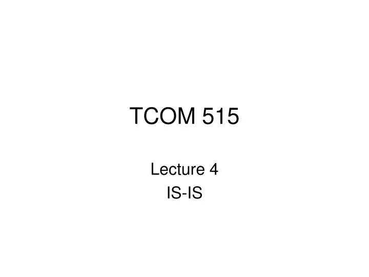
TCOM 515. Lecture 4 IS-IS. Objectives. IS-IS Terms IS-IS Areas/ Levels Subnetwork Independent Sub-layer Subnetwork Dependent Sub-layer IS-IS Neighbors & Adjacencies IS-IS Designated Routers IS-IS Metrics IS-IS PDUs. IS-IS Introduction.

E N D
TCOM 515 Lecture 4 IS-IS
Objectives • IS-IS Terms • IS-IS Areas/ Levels • Subnetwork Independent Sub-layer • Subnetwork Dependent Sub-layer • IS-IS Neighbors & Adjacencies • IS-IS Designated Routers • IS-IS Metrics • IS-IS PDUs
IS-IS Introduction • IS-IS - Intermediate System to Intermediate System • Developed by DEC for ISO • Can Route IP and/or CLNP - Connectionless Network Protocol • ISO 10589 • IS-IS developed at same time as OSPF. • Political factors involved in the choice of OSPF over IS-IS by the IETF • Many similarities between OSPF and IS-IS
IS-IS and OSPF • IS-IS and OSPF have many similarities: • Link state databast with use of SPF alogrithm • Hello packets used to form and maintain adjacencies • Use of areas to form a two-level hierarchical topology • Both can provide address summarization between areas • Both are classless routing protocols • Election of Designated Routers to represent broadcast networks • Both have authentication
IS-IS Terms Intermediate system (IS)- Router Designated Intermediate System (DIS) - Designated Router Pseudonode - Broadcast link emulated as virtual node by DIS End System (ES) - Network Host or workstation Network Service Access Point (NSAP) - Network Layer Address Subnetwork Point of attachment (SNPA) - Datalink interface Packet data Unit (PDU) - Analogous to IPPacket Link State PDU (LSP) - Routing information packet
IS-IS Packet Types • IS-IS Hello Packets (IIH) • Level 1 LAN IS-IS Hello • Level 2 LAN IS-IS Hello • Point-to-point Hello • Link State Packets (LSP) • Level 1 and Level 2 • Complete Sequence Number packets (CSNP) • Level 1 and Level 2 • Partial Sequence Number Packets (PSNP) • Level 1 and Level 2
IS-IS Areas/Levels • Two types of area - defined by levels • Level 2 - like Area 0 of OSPF, form backbone • Level 1 - non-backbone areas • A router can be L1, L2 or L1/L2. • An L1 router only knows about its area. • An L1/L2 router must maintain separate L1 and L2 Link State Databases, L2 routes are not advertised to L1 routers • An L2 routers, L1/L2 routers and their interconnecting links form the IS-IS backbone.
Areas IS-IS Areas Example Area 49.001 L1 Level-1 Area L1L2 Level-2 Backbone Area 49.003 Area 49.0002 Level-1 Area Level-1 Area L1L2 L1L2 L1 L1
Hierarchical Routing Backbone Area 49.0002 Area 49.001 Level-1 Routing Level-1 Routing Level-2 Routing • IS-IS supports 2-level routing hierarchy • Routing domain is carved into areas. • Routing in an area is level-1. • Routing between areas is level-2
IS-IS Network IDs • Area ID - area address associated with an entire router, not a link • Each router can have up to three area addresses • Used by Level 2 routing • System ID - router ID like, uniquely identifies an IS-IS router • Used by Level 1 routing • NET - Network Entity Title - made up of an Area ID, a System ID and an NSAP Selector • NSAP - Network Service Access Point • RFC 1237 - specifies NET configuration
IS-IS Network Sublayers IS-IS Network layer divided into two sublayers to allow it to adapt to different types of data links and subnetworks Subnetwork Independent Sublayer - provides consistent, uniform network services to Transport layer Subnetwork Dependent Sublayer - accesses the services of the data link layer on behalf of the Dependent sublayer Transport Network Data Link
IS-IS Dependent Sublayer Subnetwork Dependent Sublayer - hides the characteristics of the different kinds of data links from the Independent Sublayer Dependent Sublayer Responsibilities: • transmission and reception of PDUs • exchange of IS-IS Hello PDUs • discover neighbors and form adjacencies • adjacency maintenance • link demultiplexing and transfer of IP packets to IP process and OSI PDUs to OSI process
IS-IS Hellos & Adjacencies IS-IS Hellos are sent every 10 seconds by default. Hellos are used to discover neighbors, as keepalives for the adjacencies, and includes a hold timer to tell its neighbor how long to wait for another Hello before declaring the neighbor dead. Hello information identifies the source router, its capabilities, and describes the interface parameters on which the Hello was sent. Adjacency - formed between two neighbors after they agree on router and interface capabilities, but can only be formed between routers of the same level
IS-IS Neighbors IS-IS Neighbor Table has several fields: System ID - the IS-IS system ID that uniquely identifies each router Interface - the local interface over which the adjacency is formed State - each neighbor can either the Initialization state (INIT) that the neighbor is known but not adjacent or the Up state (UP) the neighbor is adjacent Priority - the router priority for the IS-IS designated router election Circuit ID - based on the System ID and Pseudonode ID
IS-IS Designated Router Designated Router or Designated IS-IS - elected on broadcast multi-access network to that each router doesn’t have to advertise an adjacency with every other router on the LAN. Each router does still have an adjacency to every other router. The network itself is considered a router, a psuedonode to which every router including the DR advertises a link to it. Each router floods its Link State PDUs (LSPs) to all its neighbors and the DR uses Sequence Number PDUs (SNPs) to ensure reliability of the flooding. IS-IS routers have an L1 priority and an L2 priority between 0 and 127 with a default value of 64 which is configurable. A value of 0 makes the router ineligible to become the designated router DR. If the DR fails, a new DR is elected, no back-up. Routers advertise their priority in the appropriate Hellos. The router with the highest priority wins, if there is a tie, the highest System ID become the DR. The DR assigns the LAN ID - combo of System and Psuedonode IDs.
Independent Sublayer The Subnetwork Independent Sublayer delivers the packets throughout the internetwork and how these services are offered to the transport layer. The routing function is divided into four processes: • Update process • Decision process • Forwarding process • Receive Process The Forwarding and Receive process are used for the transmitting and reception of PDUs and relate more to CLNS than IP so we won’t worry about them. See ISO 10589 for more.
Update Process The Update process of the routing function is responsible for constructing the L1 and L2 Link State Databases. IS-IS Link State Packets (LSPs) - contain values for: • Remaining Lifetime - begins at Max Age and decrements to zero over time - default 1200 seconds • Sequence Number - starts at 1 and orders the LSAs from the router • Checksum - Used to check LSA for correct info, if there is an incorrect checksum, the Remaining Lifetime is set to 0 and flooded throughout the network to purge it from all the routers.
Update Process 2 SNP - Sequence Number PDUs PSNP - Partial SNP • Used to acknowledge each LSP as it receives it. • Sent on a Point-to-Point link. • Identifies the LSP by its: • LSP ID • LSP Sequence Number • LSP Checksum • LSP Remaining Lifetime • If the LSP is not acknowledged by the timer, the router resends the LSP on the link. The default timer is 5 seconds.
Update Process 3 SNP - Sequence Number PDUs CSNP - Complete SNP • Used on broadcast subnetworks. • Designated router multicasts a CSNP. • This CSNP describes every LSP that is currently in the DR’s Link State Database. • When a router receives a CSNP, it compares the LSPs described in the CSNP with its own Link State Database. • If the router has a newer version of an LSP or an LSP not in the CSNP, it multicasts the LSP onto the network. • If the router has an older version or is missing a copy of an LSP in the CSNP, it updates its database.
IS-IS Link State Database The IS-IS Link State Database fields are: LSPID - the LSP ID - The router System ID plus the Psuedonode ID plus LSP number (used for fragmentation of the LSP) LSP Seq Num - LSP Sequence Number - the sequence number field from the LSP packet LSP Checksum - The checksum field from the LSP packet LSP Holdtime - Remaining Lifetime of the LSP, reset to 1200 seconds on update ATT/P/OL - ATT - Attached bit - set to 1 by L1/L2 routers, P - Partition bit - router has partition repair capability, OL - Overload bit - set to 1 if router is having memory overload problems.
IS-IS Route Metrics The IS-IS route metrics have a value between 0 and 63: Default - supported and understood by every IS-IS router Delay - optional metric reflecting transit delay of subnetwork Expense - optional metric reflecting monetary cost of using the subnetwork Error - optional metric reflecting the residual error probability of the subnetwork Cisco only supports the default metric. Each metric will determine the optimal router for each destination. So with all four metrics being used that is four SPF calculations for each destination.
IS-IS Decision Process The IS-IS Decision Process uses the Link State database built by the Update process to calculate the SFP for each destination. A default metric of 10 is assigned to every interface by default but can be changed. If left at 10, with all interfaces equal, metric becomes a hop count. Total cost of a route is the sum of metrics of outgoing interfaces along the path. Max is 1023. L1 and L2 routes are calculated for each destination. L1 path is preferred over an L2 path. Up to six equal costs paths will be put into the routing table, IS-IS will load balance over the paths. Routes are also classified as internal - destination within the domain or external - destination not in domain.
IS-IS PDUs IS-IS has three catagories of PDUs that include 9 different types, identified by a five-bit type number. Hello PDUs • Level 1 LAN IS-IS Hello PDU 15 • Level 2 LAN IS-IS Hello PDU 16 • Point-to-point IS-IS Hello PDU 17 Link State PDUs • Level 1 LSP 18 • Level 2 LSP 20 Sequence Number PDUs • Level 1 CSNP 24 • Level 2 CSNP 25 • Level 1 PSNP 26 • Level 2 PSNP 27
IS-IS PDU Header The PDU header is 8 octects and appears at the beginning of all IS-IS PDUs. Below is the format: 0 8 bits
IS-IS PDU Header 2 The PDU header has 8 fields: Intradomain Routing Protocol Discriminator - ISO constant to 0x83 for IS-IS PDUs. Length Indicator - length of fixed header in octets Version/Procotol ID Extension - set to 1 ID Length - length of System ID field of NSAP address and NETs within the domian 1-8 - System ID of length of value in octets 0 - System ID of 6 octets - most common 255 - Null System ID field - 0 octets PDU Type - Type listed previously - 9 types Version - set to 1 Reserved - not yet used - set to 0 Maximum Area Address - number of area addresses permitted in IS-IS area PDU Specific fields - depend on PDU type, are considering part of header
IS-IS CLV Types CLV stands for Code/Length/Value and are the variable-length fields in the PDUs after the PDU header. The CLV Code specifies the information being carried in the Value field, while the Length field specifies the length of the Value field. The Value field is the information used for IS-IS routing. Area Addresses 1 IS Neighbors (LSPs) 2 ES Neighbors 3 Partition Designated Level 2 IS 4 Prefix Neighbors 5 IS Neighbors (Hellos) 6 Padding 8 LSP Entries 9 Authentication Information 10 IP Internal Reachability Info 128 Protocols Supported 129 IP External Reachability Info 130 Inter-Domain Routing Protocol Info 131 IP Interface Address 132 Authentication Information 133
Summary • IS-IS Areas • IS-IS Levels • IS-IS PDUs • IS-IS Neighbors • IS-IS Network Sublayers • IS-IS Update & Decision Processes • OSPF vs IS-IS