Download
1 / 35
410 likes | 804 Views
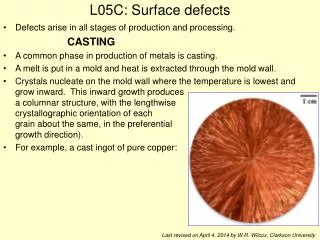
Influence of surface defects and metallurgical defects on the fatigue strength of ductile iron. Characteristic surface of a fatigue fracture. Borderline between the fast fracture area and the fatigue fracture area. Crack start point. Characteristic surface of fatigue fracture.

E N D
Influence of surface defects and metallurgical defects on the fatigue strength of ductile iron
Characteristic surface of a fatigue fracture Borderline between the fast fracture area and the fatigue fracture area Crack start point
Characteristic surface of fatigue fracture Crack start point Borderline between the fast fracture area and the fatigue fracture area
State of stress at different fatigue loadings Push/pull Bending Torsion Surface effect
Cast parts with different fatigue loadings Bending Push/pull Torsion Crankshaft Axle arm Piston rod
Fatigue fracture caused by an inclusion in the surface zone of GJS 600-3 with casting skin Inclusion
Fatigue fracture caused by Dross in the surface zone of GJS 400-15
Different fatigue testing machines Resonant testing machine Rotary bending testing machine Source: Walter + Bai AG Source: Russenberger Prüfmaschinen AG
Samples of specimen for fatigue testing by ASTM E 466 4 point bending equipment Round specimen Geometrical rated break point Constant test area Flat specimen
Microstructure of GJS 400 in as cast condition Microstructure of GJS 400 with graphite flotation 25x 16x
Influence of the surface and the casting skin on the bending fatigue strength of ferritic nodular iron 350 300 250 200 Stress Amplitude [MPa] 150 100 50 0 1,E+04 1,E+05 1,E+06 1,E+07 Cycles [N] GJS 400 without defects & machined surface GJS 400 without defects & casting skin GJS 400 with graphite flotation & casting skin
Microstructure of GJS 400 with 61 % Nodularity Microstructure of GJS 400 with 70 % Nodularity 50x 50x
Influence of structural defects on the compression-tension fatigue strength of ferritic nodular iron 350 300 250 200 Stress Amplitude [MPa] 150 100 50 0 1,E+04 1,E+05 1,E+06 1,E+07 Cycles [N] GJS 400 without defects GJS 400 with 61% Nodularity GJS 400 with 70% Nodularity
Influence of structural defects on the rotary bending fatigue strength of ferritic nodular iron 350 300 250 200 Stress Amplitude [MPa] 150 100 50 0 1,E+04 1,E+05 1,E+06 1,E+07 Cycles [N] GJS 400 without defects GJS 400 with 61% Nodularity GJS 400 with 70% Nodularity GJS 400 with nonmetallic inclusions
Microstructure of GJS 700with 100 % pearlite Microstructure of GJS 700 with 20 % ferrite 100x 100x
Influence of structural defects on the compression-tension fatigue strength of pearlitic nodular iron 350 300 250 200 Stress Amplitude [MPa] 150 100 50 0 1,E+04 1,E+05 1,E+06 1,E+07 Cycles [N] GJS 700 with 100 % pearlite GJS 700 with 20 % ferrite
450 400 350 300 250 Stress Amplitude [MPa] 200 150 100 50 0 1,E+04 1,E+05 1,E+06 1,E+07 Cycles [N] GJS 700 without defects GJS 700 with 1,25 % spiky graphite Influence of graphite defects on the rotary bending fatigue strength of pearlitic nodular iron
Abstract 1 > The appearance of cracks at the casting skin normally are caused by single defects like sand, dross or slag with an Ø < 1 mm. > Single defects in the cast skin are more significant than anomalies in the microstructure at the casting skin and in the cast wall. > The blasting of the cast skin improve the bending fatigue strength up to 50 % compared to non-blasted cast surfaces. > Blasted surfaces have a 25 % reduced bending fatigue strength compared to machined surfaces. > The prevention of “big defects” is state of the art, but the producing of castings completely without failures are unrealistic. The design of the castings have to tolerate different micro structural and surface defects.
ADI heat treatment of the samples Austenitizing: 890°C / 210 min Quenching: salt bath Holding: 380°C / 150 min Microstructure of base material afterheat treatment (500 : 1)
0,8 0,7 0,6 0,5 0,4 0,3 0,2 Reference 0,1 0 0,040 0,045 0,050 0,055 0,060 0,065 0,070 0,075 0,080 Mg-content in % Influence of Mg-content on the volume of non metallic inclusions Non metallic inclusions (%)
100 80 60 Typ III (1) Reference 40 20 Typ III (2) 0 0 0,01 0,02 0,03 0,04 0,05 Mg-content (%) Nodularity (%) Graphite type III (%) Influence of the Mg-content on the nodularity and graphite type III Percentage
Influence of Mo-content on carbide formation 0,40 0,35 0,30 0,25 Carbide content (%) 0,20 0,15 0,10 0,05 0,00 0 0,1 0,2 0,3 0,4 0,5 0,6 0,7 0,8 Mo-content (%)
Mechanical values of all test variants 1000 7 900 6 800 5 700 600 4 500 Fracture elongation (%) Strength (MPa) 3 400 300 2 200 1 100 0 0 Basematerial Nonmetallic(1) Nonmetallic(2) Graphite typ III Carbides (1) Carbides (2) (1) (2) Variants Rm [MPa] Rp0,2 [MPa] A [%]
Fatigue strength 350 300 250 200 Stress amplitade (MPa) 150 100 50 0 Casting skin defect Basematerial Graphite type III Carbides (1) Carbides (2) Non metallic inclusions (1) (2) (2) (1) (as cast) (shot blasted) Variants Bending fatigue strength [MPa] Compression-tension fatigue strength [MPa] Rotary bending fatigue strength [MPa]