Download
1 / 11
110 likes | 117 Views
Explore the structure and evolution of the universe through micro arc-second imaging in the x-ray region of the spectrum. Discover black hole accretion disks, stellar coronae, cataclysmic variables, and more.

E N D
MAXIM Periscope Module Science Liaison H. John Wood (Read by Jennifer Bracken) 25 April 2003
Structure and Evolution of the Universe • In order to study the structure and evolution of the universe – micro arc-second imaging will be required • X-ray imaging can pierce the dusty centers of galaxies in order to study some of the most energetic events in creation • What can you see with micro arc-second imaging in the x-ray region of the spectrum? • accretion disks of black holes • stellar coronae and interacting binaries • Cataclysmic variables and X-ray binaries • Distant Active Galactic Nuclei
Two globular clusters These globular clusters both have giant black holes at their centers
Purpose of the Study • An optics – oriented study • Are the mirrors impossible to make? • Are actuators available to move the mirrors by nm steps over microns of range? • Can the thermal and structural environment be benign enough to maintain mirror figure and stability? • Is internal metrology needed – if so how to implement? • What would the alignment procedures be? • Trade study on the mirror sizes and the impact on the number and sizes of the spacecrafts • What are the cost, mass and power inputs?
The Collecting Area of Chandra for 1/10 The Cost • Chandra has 0.5 arc sec resolution and its mirrors cost $400M • This study has shown that it is possible to build a microarcsec imaging telescope with the same collecting area as the current Chandra for 1/10 its cost • The study has also shown how the engineering can be done to allow X-ray imaging and spectroscopy in formation flying • The nature of the detector allows imaging over a large range of energies simultaneously
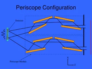
Full MAXIM Design Overview • Configuration at L2 • Hub and 25 free-flyers form an “objective” over a one-kilometer diameter area • 4-mirror grazing-incidence periscopes in each spacecraft reflect x-rays to a detector ship 20,000 km away • Alignment of the optical beams and phasing of them on the detector allows formation of an image • Collecting area is 1000 square centimeters – the entrance aperture is 18.25 by 0.489 cm for each periscope • Thus, each of the 25 free flyers will have 4 periscopes and the hub will have 12 periscopes for a total of 112 periscopes
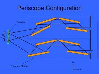
Full MAXIM Design Overview con’t • Optical design • 4-mirror grazing-incidence periscope design simulates the properties of a thin lens: optical tolerances are relaxed in comparison to a typical two-mirror X-ray design • In the periscope, each flat mirror is used at 1 degree angle of incidence • Mirrors are known by their numbers in sequence they are hit by X-rays (#1 entrance, #2, #3 and #4 exit) • Flat mirrors are 30 x 20 x 5 cm with the optical reflection on the 30 x 20 face (gold coat) • Graze direction is in the 30 cm direction and requires figure quality of lambda/300 (633nm) • Orthogonal direction only requires lambda/10 • Beam steering with roll and pitch of the exit mirror (#4) • Optical path length phasing by motion of a daughter bench carrying mirrors #2 and #3 relative to the main optical bench which hold #1 and #4 with its actuators
Side View of a Periscope Module Mirrors in lilac; bench in fuchsia; daughter bench in orange with its actuator in gold
A Dual-Periscope Module Note the entrance slots right with one shutter open & one closed
Up Next • The Systems Engineering Report will be presented by Deborah Amato