Download

1 / 31
320 likes | 413 Views
Learn how to use crimping pliers to make custom Vex cables & connectors. Gather tools & materials, prepare cable, strip wires, and securely crimp for effective results.

E N D
CRIMPINGIntroduction • This presentation is the companion to “Background / Resources / Crimping Guide” slide show • For more detailed instructions, watch the slide show
CRIMPINGOverview • In this presentation you will learn: • How to use crimping pliers • How to create custom cables and connectors for Vex • How to determine your cable / connector needs • In this presentation you will make: • A 7½ foot motor extension cable • Will connect a motor to the Vex microcontroller
CRIMPING Making custom cables • Why? • Standard Vex cables are limited • Might need different lengths • Might need more extension wires than included in your kit • How? • Manufacturing your own cable is simple! • You will use a crimping tool
CRIMPING Determine your needs • Ask yourself: • What are you trying to do? • What materials do you have or need? • What is the configuration of the cable needed to complete your task? • What length of cable do you need?
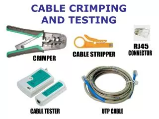
CRIMPING Gather tools • You will need: • Crimping tool • Molex 11-01-0208 Hand Crimper • Supports 22 – 24 and 30 – 36 AWG • Wire strippers • Tape measure
CRIMPING Gather materials • Vex cable parts: • 22 AWG wire, 3 conductor cable • Male Molex pins • Female Molex pins • Crimp housing
CRIMPING Gather materials • More on your cable: • AWG (American Wire Gauge) is simply a measure of the wire’s thickness • Notice the conductor cable has 3 wires inside (all 22 AWG) • This type of cable is used for input and output in the Vex system • If you do not have this wire available, substitute with 3 (22 AWG) differently colored wires
CRIMPING Prepare the cable • Measure the length of cable you need • Make sure to leave yourself 6” of extra length, in case of a mistake • For this example, we need a cable 7½ feet long; so it should be 8 feet total after adding the 6 inches • If your cable needs to be a more exact length, be very accurate; once the pins have been locked into position, they cannot be removed
CRIMPING Cut cable • Cut the length of cable you measured • Wire strippers usually double as wire cutters; look for a cutting edge on the blade
CRIMPING Separate wires • Use wire strippers to remove 1/8” of insulation from each conductor (wire) • Make sure to leave 1½ inches from the end so that you can strip them • This cable has PVC tubing around the three wires (the grey covering) • Trim this PVC covering 1½ inches around the three wires • After trimming the covering, separate the three wires manually
CRIMPING Strip wires • Use wire strippers to remove 1/8” of insulation from each conductor (wire) • Make sure to place the wire into the proper gauge hole in your wire strippers • Squeeze handles until the wire strippers bite through the insulation • Slide insulation off the end of the wire, leaving the metal conductor exposed
CRIMPING Step 1 • We will now begin making the Vex connector • Become familiar with your crimper • Make sure you know how to squeeze the handles until the crimper unlocks
CRIMPING Step 1 continued • Use the gauge guide (shown at right) to determine which site to use for your gauge of wire • In our case, we must use site A (because we have been using 22 AWG wire)
CRIMPING Step 2 • The crimper holds the pin in place for you during crimping • Locate the spring loaded clamp below the jaw of the crimper • Raise the clamp with your finger, as shown
CRIMPING Pins • Male pins plug into female pins • For our example, we want our wire to connect the Vex microcontroller and a motor Female Male Connects wire to Vex microcontroller Connects wire to motor
CRIMPING Step 3 • Choose a gender of pin for this connector • Place the pin into the open slot on the crimper while the clamp is raised • - The male or female end goes in first • - The pin cradle should face up or open upward
CRIMPING Step 3continued • The pin should move forward until the front of the pin cradle is against the spring loaded clamp properly loaded pin
CRIMPING Step 4 • Release the spring loaded clamp • This will lock the pin in position • The pin is designed to fit into this crimper • - If your pin is crooked, or if the clamp does not clamp down properly, simply lift up the clamp and try again
CRIMPING Step 5 • Notice that there are “teeth” on both male and female pins • The wire must be positioned using these teeth as guides • - Inner set of teeth should be over exposed metal wire • - Outer set of teeth should be over insulation Inner teeth: close around bare wire Outer teeth: close around insulation
CRIMPING Step 5 continued • Using the guides in the first part of step 5, place the wire in pin cradle, as shown • - The bare wire should touch the clamp
CRIMPING Step 6 • Squeeze the crimper’s handles to secure the wire into the pin • - Make sure to hold the wire steady so that does not move while crimping • - Squeeze the handles until you feel them release
CRIMPING Step 7 • Remove the wire from the crimper • - Push on the bottom of the clamp to release the pin • - Once you have reached this state, you cannot separate the wire from the pin without cutting the wire
CRIMPING Step 8 • Repeat the steps 1 through 7 for each of the two remaining wires, as shown • - Use the same gender pins on all three wires
CRIMPING Housing • A crimping housing unit is shown at the right • - Once the pins have been inserted into the housing, they cannot be removed • - Pins only fit one way into this particular housing unit • - Both male and female pins can fit into this particular housing unit Insert pins here
CRIMPING Step 9 • Place the wires in the crimping housing • - The wires must go in order by color, as shown: black, red, and white • - Once you complete this step, you will not be able to remove the wires from the crimping housing without cutting them
CRIMPING Step 10 • Line up the wire with the housing • - Make sure the locking tab on the pin cradle is facing up, as shown
CRIMPING Step 10 continued • Slide the pin into the housing, as shown, until the pin is locked into position • - Do not force the wire • - The pin might make a clicking sound when it has locked into position
CRIMPING Step 10 continued • To test if your pin is locked into the crimp housing, gently tug on the wire, as shown
CRIMPING Step 11 • Insert the remaining pins into the housing • - Remember the order of colors: black, red, white
CRIMPING Step 12 • Repeat steps 1 through 12 for the other side of the wire • Check your completed connector against the official Vex connector
CRIMPING Testing • Connect the female connector to the motor • Connect the male connector to the Vex microcontroller • Be sure not to insert these wires backwards; refer to the pictures at the right • Turn on your robot and test the motor with your radio control transmitter