Download
1 / 3
30 likes | 135 Views
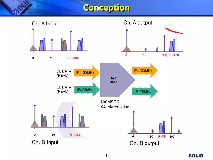
Conception. Ch. A output. Ch. A Input. DAC 5687. IF=120MHz. IF=120MHz. DL DATA (REAL). IF=75MHz. UL DATA (REAL). IF=75MHz. 100MSPS X4 interpolation. Ch. B Input. Ch. B output. Signal Processing in DAC-DL. Ch. A(120MHz). DAC Mode X4L Mode First FIR High Pass CM = Fdac/2

E N D
Conception Ch. A output Ch. A Input DAC 5687 IF=120MHz IF=120MHz DL DATA (REAL) IF=75MHz UL DATA (REAL) IF=75MHz 100MSPS X4 interpolation Ch. B Input Ch. B output
Signal Processing in DAC-DL Ch. A(120MHz) DAC Mode X4L Mode First FIR High Pass CM = Fdac/2 -A/A/-A/A -B/B/-B/B -50 0 50 Fs =100 200 400 FIR1 High Pass Mode 2-over -50 0 50 100 Fs = 200 400 2-over FIR3 In case of DL, IF=120MHz is set by using above configuration. -50 0 50 100200 Fs=400 Fdac/2 Shift -50 0 50 100200 Fs=400 Fdac IF out -50 0 50 100 IF =120 200 Fs=400 DC noise
Signal Processing in DAC-UL Figure 1 input Ch. B(75MHz) input -50 0 50 Fs =100 200 400 • 0) In case of Figure 1 is for input for Channel B, is it possible as Figure 2? • Is it possible that the Channel A for DL IF=120-MHz and Channel B for UL IF=75MHz? • 2) In case of same as Channel A, If set usb(data to DACB is inverted to generate upper-sideband output.) of Addr • 0x04h, What results it give? Figure 2 output -50 0 50 IF=75100200 Fs=400 Fdac