Download

1 / 20
200 likes | 352 Views
Introducing the Specifications of the Metro Ethernet Forum. Introducing the Specifications of the Metro Ethernet Forum. MEF 2 Requirements and Framework for Ethernet Service Protection MEF 3 Circuit Emulation Service Definitions, Framework and Requirements in Metro Ethernet Networks

E N D
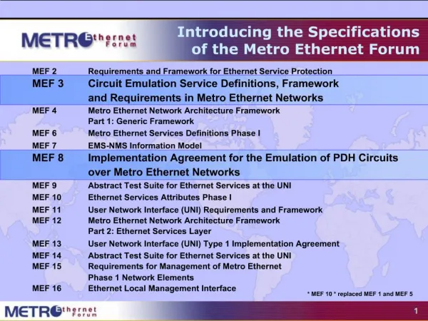
Introducing the Specifications of the Metro Ethernet Forum MEF 2 Requirements and Framework for Ethernet Service Protection MEF 3 Circuit Emulation Service Definitions, Framework and Requirements in Metro Ethernet Networks MEF 4 Metro Ethernet Network Architecture Framework Part 1: Generic Framework MEF 6 Metro Ethernet Services Definitions Phase I MEF 7 EMS-NMS Information Model MEF 8 Implementation Agreement for the Emulation of PDH Circuits over Metro Ethernet Networks MEF 9 Abstract Test Suite for Ethernet Services at the UNI MEF 10 Ethernet Services Attributes Phase I MEF 11 User Network Interface (UNI) Requirements and Framework MEF 12 Metro Ethernet Network Architecture Framework Part 2: Ethernet Services Layer MEF 13 User Network Interface (UNI) Type 1 Implementation Agreement MEF 14 Abstract Test Suite for Ethernet Services at the UNI MEF 15 Requirements for Management of Metro Ethernet Phase 1 Network Elements MEF 16 Ethernet Local Management Interface * MEF 10 * replaced MEF 1 and MEF 5
Introduction Subscriber Site Subscriber Site MEF 11 User Network Interface (UNI) Requirements and Framework Purpose Defines a split demarcation function between the customer (Subscriber), and the Service Provider Audience Equipment Manufacturers building devices that will carry Carrier Ethernet Services. Useful for Service Providers architecting their systems. Ethernet Services “Eth” Layer Service Provider 1 Metro Ethernet Network Service Provider 2 Metro Ethernet Network Subscriber Site Subscriber Site ETH UNI-N ETH E-NNI ETH E-NNI ETH UNI-N ETH UNI-C ETH UNI-C ETH UNI-N ETH UNI-N UNI: User Network Interface, UNI-C: UNI-customer side, UNI-N network side NNI: Network to Network Interface, E-NNI: External NNI; I-NNI Internal NNI
MEF 11: UNI Specification • A Specification • Defines a split demarcation function between the customer (Subscriber), and the service provider (Network) • Each maintains its own side independently of the other. • UNI Types • Type 1: Manual configuration of the CE side only- completely compatible with all existing Ethernet customer equipment • Type 2: Allows the UNI-N to provision, configure, and distribute EVC information and the associated service attributes to the CE • Type 3: Allows the CE to request, signal and negotiate EVCs and its associated Service Attributes to the UNI-N.
UNI - Network Location • An access network may exist between the subscriber and the MEN • In that case the UNI is still co-located at the subscriber edge • UNI-C is always IEE802.3 PHY connected • The reference point between the access network and the Provider Edge (PE) equipment is called Service Node Interface (SNI) • The SNI definition is not in the cope of MEF 11 • UNI-N functional components which implement the Service Provider side of the UNI functions may be distributed over an access network
Scope of UNI Framework UNI Reference model • MEF 11 Defines the functions of each • Defines the supporting requirements
Plane Functions & Requirements • Data Plane • Requires and 802.3PHY, supports 802.1Q/p tagged frames • Allows VLAN ID and COS information to be sent from subscriber to the MEN • Control Plane • Provides communication link between the subscriber and network side • Designed to Allow for Dynamic service contract set-up and negotiation as well as service provisioning • Management Plane • Allows for Device Configuration, Service OAM, and Service load-balancing/restoration • Allows for greater degree of managed service offering by the carriers • Allows for greater customer insight into the service level being delivered by the MEN
Potential for more value added services EMS Interface • Demonstrates the three UNI functions distributed on either side of the UNI • Allows for transport multiplexing (TMF) of separate UNI-C ETH Access links on a single underlying transport (TRAN) terminated at a single UNI-N ETH Access Link Management plane Management plane Management plane Management plane ETH Layer Control plane Control plane Service Frame Flow Data plane Control plane Data plane Data plane Cont rol plane Data plane TRAN Layer TRAN TRAIL UNI-C UNI-N UNI Reference Point
UNI Types MEF has defined various UNI functionality • Type 1 • Manual configuration of the CE side only- completely compatible with all existing Ethernet customer equipment • Type 2 • Allows the UNI-N to provision, configure, and distribute EVC information and the associated service attributes to the CE • Type 3 • Allows the CE to request, signal and negotiate EVCs and its associated Service Attributes to the UNI-N.
UNI Defined Service Attributes • UNI Identifier, • Physical Layer (speed, mode, and physical medium), • MAC Layer, • Service Multiplexing, • UNI EVC ID, • CE-VLAN ID/EVC Map, • Maximum number of EVCs, • Bundling, • All to One Bundling, • Bandwidth Profiles, and • UNI Layer 2 Control Protocol Processing.
EVC Defined Service Attributes • EVC Type (Point-to-Point or Multipoint-to-Multipoint), • UNI List, • Service Frame Delivery, • CE-VLAN ID Preservation, • CE-VLAN CoS Preservation • Layer 2 Control Protocol Processing, and • EVC related Performance
UNI General Requirements • UNI Type 1 MUST allow UNI-C of Subscriber equipments to connect to a UNI-N of MEN using an IEEE 802.3 2002 conforming interface. • UNI Type I MUST allow UNI-C of Subscriber equipments, conforming to IEEE 802.1Q [5] and IEEE 802.1D [6], to connect to a UNI-N of MEN. • UNI Type I MUST allow UNI-C of Subscriber equipments, implementing IEEE 802.3 end stations e.g. routers, to connect to a UNI-N of MEN. • UNI Type 1 UNI-Ns MUST support the full range of CE-VLAN Ids, in accordance with IEEE 802.1Q tag.
UNI Physical Requirements UNI Type 1 MUST support at least one of the following IEEE 802.3 Ethernet PHYs: • 10BASE-T in Full-duplex mode • 100BASE-T including 100BASE-TX and 100BASE-FX in Full-duplex mode • 1000BASE-X including 1000BASE-SX, 1000BASE-LX, and 1000BASE-T in Full-duplex mode • 10GBASE-SR, 10GBASE-LX4, 10GBASE-LR, 10GBASE-ER, 10GBASE-SW, 10GBASE-LW, and 10GBASE-EW in Full-duplex mode
UNI Type 1 Data Plane Requirements • UNI Type 1 MUST allow sending Subscriber’s IEEE 802.3-2002 compliant service frames across the UNI. • When multiple EVCs are supported by UNI-N, UNI Type 1 MUST allow mapping of Service Frames to corresponding EVCs. • UNI Type 1 MUST allow the mapping of Service Frames to the following types of EVCs: • Point-to-Point EVC • Multipoint-to-Multipoint EVC • UNI Type 1 MUST support an option for ingress bandwidth profile across the UNI. • UNI Type 1 MUST be transparent to higher layer protocols.
UNI Type 1 Data Plane Requirements • UNI Type 1 MUST allow manual configuration to set-up or tear-down EVCs across the UNI • UNI Type 1 MUST allow manual configuration to modify the service attributes associated with the EVCs across the UNI • UNI Type 1 MUST allow manual configuration to modify the ingress bandwidth profile across the UNI, where the modification may result in increment or decrement of bandwidth • If Bandwidth Profile Parameter CIR is supported, UNI Type 1 MUST allow manual configuration to modify CIR in the following granularities: • 1Mbps steps up to 10Mpbs • 5 Mbps steps beyond 10Mbps and up to 100Mbps • 50 Mbps steps beyond 100Mpbs and up to 1Gbps • 500 Mbps steps beyond 1Gbps
UNI Type 1 Control Requirements • UNI Type 1 MUST support manual configuration of following service parameters at UNI-C and UNI-N. • CE-VLAN ID/EVC Map allowing mapping each Subscriber service frame into an EVC. • Parameters of Ingress bandwidth profile per UNI • Parameters of Ingress bandwidth profile per EVC • Parameters of Ingress bandwidth profile per CoS • CoS Identifiers • Handling of UNI Layer 2 control protocols, where the handling may include: • Tunneled through EVC • Discarded, or • Processed • UNI Type 1 MUST support failure detection based on failure detection mechanisms of IEEE 802.3ah.
UNI Type 2 Requirements • UNI Type 2 UNI-C and UNI-N MUST be backward compatible with UNI Type 1. • UNI Type 2 UNI-C and UNI-N MUST support sending Ethernet OAM frames, as required by UNI Type 2 management plane, across the UNI. • UNI Type 2 UNI-C and UNI-N MUST support the service parameters to be communicated from UNI-N to UNI-C • UNI Type 2 UNI-C and UNI-N MUST support the following Ethernet OAM mechanisms between UNI-C and UNI-N such that UNI can be managed: • Connectivity verification which helps in establishing connectivity status between UNI-C and UNI-N. • Communicate the EVC availability status to the UNI-C.
UNI Type 3 Requirements • UNI Type 3 UNI-C and UNI-N MUST be backward compatible with UNI Type 2 and UNI Type 1.
Summary and Next Actions • After reading this document you should now be familiar with • The main MEF architecture functional components for the Ethernet layer • Relationships between functional model components • Relationships between subscriber and provider function • Next Actions • This introduction to the specification should be read along with the other related introductions and specifications and become familiar with the UNI/NNI elements • ITU-T recommendation G.8010 is also recommended reading for implementation of Carrier Ethernet Services over native Ethernet • For equipment manufacturers the next step is to read the specification and use the reference model as the basis for implementation. • The implementation of actual infrastructure within Access
For Full Details … Subscriber Site Subscriber Site Subscriber Site Subscriber Site Video Source … visit www.metroethernetforum.org to access the full specification Metro Carrier Ethernet Internet Global/National Carrier Ethernet Access Carrier Ethernet Hosts, Legacy Services, Remote Subscribers etc Service Provider 1 Metro Ethernet Network Service Provider 2 Metro Ethernet Network