Download
1 / 14
140 likes | 412 Views
Etching and Depostion: The Effect on Profiles and Etching Yeild Curves for Oxide Etching. Abstract authors: Ohseung Kwon, Weidong Jin and Herbert H. Sawin MIT. Presented by : Venugopal Krishnardula for EE7730, Auburn university. Topic.

E N D
Etching and Depostion: The Effect on Profiles and Etching Yeild Curves for Oxide Etching Abstract authors: Ohseung Kwon, Weidong Jin and Herbert H. Sawin MIT Presented by : Venugopal Krishnardula for EE7730, Auburn university.
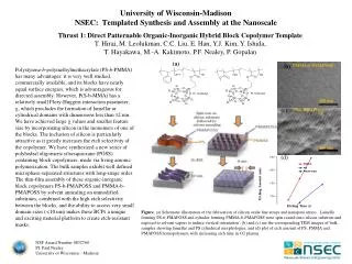
Topic • Surface kinetics study of silicon oxide etching with fluorocarbons in ICP • High denisty fluorocarbons plasma for silicon oxide etching has various ions and neutral species. Various Difficluties: • RIE lag • Etch stop • Low Selectivity of Photoresist Ref: Ohseung Kwon, Weidong Jin and Herbert H. Sawin
Research • Profile evolution modeling can provide understanding of these difficulties in etching as well as trenching ,bowing and faceting. • Measured etching and deposition rates as functions of ion bombardment energy, ion impinging angle, ion-to-neutral flux ration, which are necessary for profile evolution modeling of silicon oxide etching in ICP. Ref: Ohseung Kwon, Weidong Jin and Herbert H. Sawin
RIE lag the phenomenon in which narrower features etch slower than wider features The observed RIE lag is attributed to the collisionality of the sheath. The photoresist grating structures prevents angularly dispersed ions from striking the feature bottom and etching the polysilicon film. This reduced ion flux at the feature bottom in high aspect ratio features is believed to be the chief cause of RIE lag in commercial high density plasma etchers. Ref: Arpan P. Mahorowala and Herbert H. Sawin ,MIT
The significant ion angular dispersion causes bowing of sidewalls and the formation of microtrenches at the feature bottom. Ref: Arpan P. Mahorowala and Herbert H. Sawin , MIT
Effect of Dc Bias on Etching yield of Silicon Oxide in CHF3 plasma Below 100ev depositon dominates while above it etching dominates. The etching is done in 5 mTorr CHF3 plasma Ref: Ohseung Kwon, Weidong Jin and Herbert H. Sawin
DC Bias applied to bottom Effect of higher bottom power. This cross sectional SEM of a 0.35 mm X 1.4 mm feature is of a sample etched at a higher bottom power of 50W. The larger DC bias leads to a more directional ion flux. As a result, the sidewalls formed are more vertical compared to those in Figure 7. Ref: Arpan P. Mahorowala and Herbert H. Sawin , MIT
Etching vs Aspect ratio & Pressure • Increasing the pressure should reduce the mean free path of the neutrals, making the sheath more collisional. This in turn should lead to more angularly dispersed ions and hence more severe RIE lag Ref: Arpan P. Mahorowala and Herbert H. Sawin , MIT
Effect of ion impinging angle on Etching yield. Unlike conventional physical sputtering curve or ion-induced chemical etching without etching chemistry,oxide etching yeilds in fluorocarbon plasma show very unique shape wuth etching to depostion crossover depending on the experimental condition Ref: Ohseung Kwon, Weidong Jin and Herbert H. Sawin
Deposition Angular dependence(result of the combination of etching and deposition occuring simulataneously) Substraction of supposed etch yield from measured yeild curve gives depostion component. The resulting deposition component curve shows sputtering-like angular dependence suggesting the deposition is ion enhanced depositon process. Ref: Ohseung Kwon, Weidong Jin and Herbert H. Sawin
Conclusions • For this particular experiment below 100 deposition dominates and above it etching occurs. • Unique behaviour of angular dependence of stching yeilds of oxide • Unique shape of oxide etching yields in flurocarbon plasma with etching to deposition crossover .
Quartz Crystal Microbalance • The resonant frequency (f) of the crystal depends on the total oscillating mass, including water coupled to the oscillation. When a thin film is attached to the sensor crystal the frequency decreases. If the film is thin and rigid the decrease in frequency is proportional to the mass of the film. In this way, the QCM operates as a very sensitive balance. • http://www.q-sense.com/qcmd_tech.html