Download
1 / 8
80 likes | 228 Views
Laser Drive Needs. Total laser current I TOT = I BIAS + I MOD BIAS Current Keeps I TOT > I TH (laser “on”) I BIAS – I TH related to speed Modulation (MOD) Current Shaped by the data Larger I MOD gives larger signal. I BIAS. I MOD. I TOT. MAX3287 Evaluation Kit.

E N D
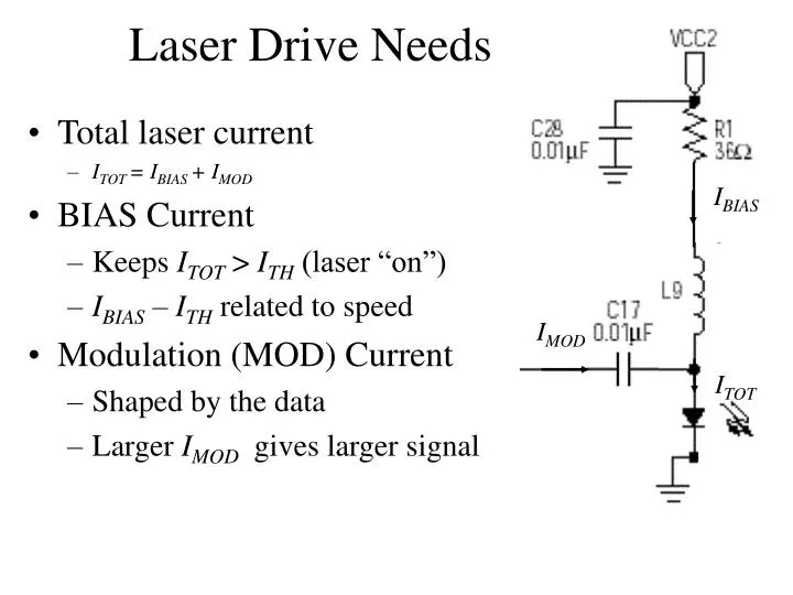
Laser Drive Needs • Total laser current • ITOT = IBIAS + IMOD • BIAS Current • Keeps ITOT > ITH (laser “on”) • IBIAS – ITH related to speed • Modulation (MOD) Current • Shaped by the data • Larger IMOD gives larger signal IBIAS IMOD ITOT
Test Setup for Maxim board • Tested to verify its functionality • Two test conducted for Maxim board • DC coupled output of Maxim board • AC coupled output of Maxim board • Equipment used • 5V power supply • SMA cables and connectors • Oscilloscope and function generator
Test Results for Maxim boardDC coupled • Near perfect open eye • Fits the compliance mask • Signifies very low SNR • Slight dip at the bottom (unexplained phenomenon)
Test Results for Maxim boardAC coupled • Again a near perfect open eye • Low SNR • Fits the compliance mask • The dip on bottom disappears (mysteriously – AC coupling?)
Circuit from unstuffed part of MAX 3287 Eval board • Remove feedback loop PD, bias adjustment PNP RED Note: Pin 2 is really “FLTDLY” NOT “POR” as in MAXIM data sheet. So it must be grounded.
Circuit from unstuffed part of MAX 3287 Eval board • Remove C25 and R27 RED • Keep all other components GREEN • Use Eval board part numbers for inductors (ferrite beads)
Design elements • Match load on OUT- with OUT+ as well as you can (R26) • Need to be able to adjust Laser DC Bias current (R1) • Need to be able to adjust Laser modulation current (R25)