Download
1 / 11
110 likes | 165 Views
Learn how to transition from 2D sketches to 3D solids through extrusion, creating depth and volume. Explore base extrusion options, part features, and extrusion types like join, cut, and intersect.

E N D
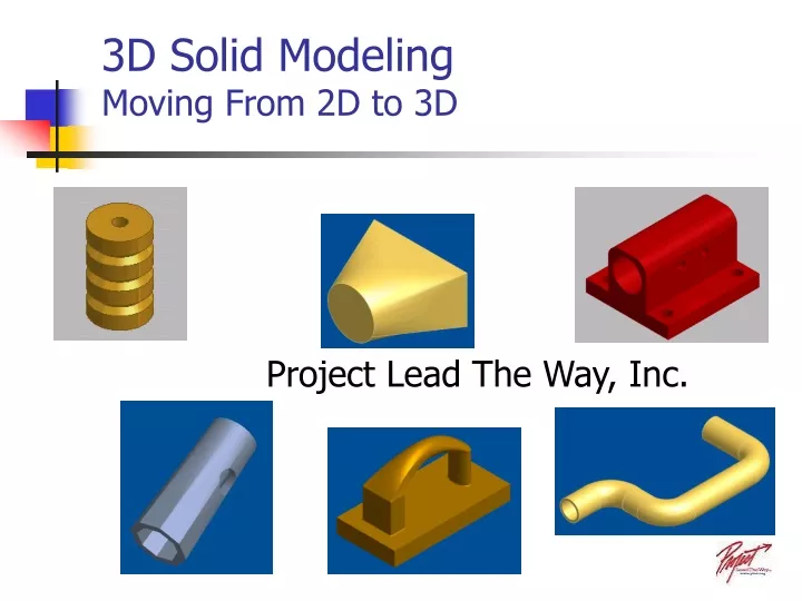
3D Solid ModelingMoving From 2D to 3D Project Lead The Way, Inc.
Extruding a 2D Sketch Solids can be created by extruding 2D sketches. Extruding the sketch gives the shape depth. The depth provides a third dimension making it a “3D solid.” This also gives the part volume = (L x W x D).
Base Extrusion Options This part was extruded with the circle as an island. This technique creates a hole.
Base Extrusion Options Both sets of geometry are selected to extrude a solid part.
Base Extrusion Options Here the circle is selected for the extrusion. The result is a cylinder.
Base Extrusion Options Flip Direction Mid-plane - extrudes in both directions
Base Extrusion Options A draft angle is applied to taper the edges as it is extruded. Draft angles are required for molded parts. Note the Draft Angle
Extrusion Types Base Feature Options Part Feature Options This applies to the first sketch that is extruded in a part. The only options refer to direction and termination. More features can be applied to change the base feature. These added extrusion options include JOIN, CUT and INTERSECT.
Extrusion Join Here a sketched feature is JOINED, or added to the BASE feature increasing its volume.
Extrude Cut A sketch can also be extruded to CUT a 3D solid. In this case the volume of the new feature is removed from the base part.
Extrude Intersect IntersectCreates a new feature from the shared volume of the extruded feature and the base part. Material not included in the shared volume is deleted. Intersect