Download
1 / 11
140 likes | 433 Views
Module 3: Analysis Techniques Topic 1: Lattice Diagrams. OGI EE564 Howard Heck. Where Are We? . Introduction Transmission Line Basics Analysis Tools Lattice Diagrams Bergeron Diagrams Metrics & Methodology Advanced Transmission Lines Multi-Gb/s Signaling Special Topics. Contents.

E N D
Module 3: Analysis TechniquesTopic 1: Lattice Diagrams OGI EE564 Howard Heck Section 3.1
Where Are We? • Introduction • Transmission Line Basics • Analysis Tools • Lattice Diagrams • Bergeron Diagrams • Metrics & Methodology • Advanced Transmission Lines • Multi-Gb/s Signaling • Special Topics Section 3.1
Contents • Lattice Diagram Construction • Axes • Wave vectors • Voltages & Currents • Example • Circuit • Lattice Diagram • Waveforms • Summary • References Section 3.1
Construction #1 0 l z r r = = 0 t d 2t d 3t d 4t d t • The lattice diagram is a tool for keeping track of the voltage & current waves as they travel back & forth along the transmission line: • The time axis runs down the page & is usually expressed in terms of the propagation delay (td) of the transmission line. • The z- (distance) axis runs across the page and extends from the source to the farthest load. • For convenience, the reflection coefficients at each discontinuity are often placed at the top of the diagram. Section 3.1
Construction #2 0 l z r r = = V(z=0) I(z=0) V(z=l) I(z=l) V0 0 I0 V1 t d I1 I5 I7 I9 I11 I3 V2 2t d I2 I4 I10 I6 I8 V3 3t d V4 4t d V5 5t d V6 6t d V1 7t d V8 8t d V1 9t d V10 10t d V11 11t d 12t d t • To show the propagation of the signal: • Use a “vector” to show the travel of the signal along the line. • Use the initial wave and the reflection coefficients to calculate the voltage amplitude for each successive reflected wave • Do the same for current. Section 3.1
Construction #3 0 l z r r = = V(z=0) I(z=0) V(z=l) I(z=l) V0- V0 V0+V1 V0+V1 +V2 I0-I1 +I2 I0 I0- I0-I1 V0 0 V0- I0- I0 V1 t d I11 I7 I9 I3 I1 I5 V2 2t d I10 I2 I8 I6 I4 V3 3t d V0+V1 +V2+V3 I0-I1 +I2-I3 V4 4t d V5 5t d V6 6t d V1 7t d V8 8t d V1 9t d V10 10t d V11 11t d 12t d t • Track the signals at the discontinuities: • Recall from superposition that the total signal (V or I) at any point on the network at a given time is the sum of all waves that have reached that point since the last signal transition (t=0). • We can now construct the voltage and current waveforms. etc. etc. Section 3.1
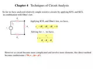
Example Circuit I RS = 25W z = l Z0 = 50W W t Z = 50 , = 3 ns 0 D VS = 5.0V z = 0 RL= 100W Analyze the low-high transition • Reflection coefficients: • Initial wave: • Final value: Section 3.1
Example Lattice I z = l W t Z = 50 , = 3 ns 0 D z = 0 0 l z W R = 25 r r (z=0) = -1/3 (z=l) = 1/3 S V(z=0) I(z=0) V(z=l) I(z=l) V = 5.0V 0.000V 0.00mA S 3.333V 0 66.7mA R = 100 W 0.000V 0.00mA T t 3.333V 66.7mA 1.111V d 22.2mA 2t 4.444V 44.5mA -0.370V d -7.41mA 3t 4.074V 37.1mA -0.123V d -2.47mA 0.041V 4t 3.951V 39.6mA d 0.82mA 5t 3.992V 40.4mA 0.013V d 0.27mA -0.005V 6t 4.005V 40.1mA d -0.09mA 7t 4.000V 40.0mA -0.002V d -0.03mA 8t <0.001V 4.002V 40.0mA d <0.01mA 9t 4.000V 40.0mA d 10t d t Section 3.1
Example Waveforms 5.0 V(z=0) 4.5 V(z=l) 4.0 3.5 3.0 voltage [V] 2.5 2.0 1.5 1.0 0.5 0.0 0 1 2 3 4 5 6 time [td] 70 I(z=0) 60 I(z=l) 50 40 current [mA] 30 20 10 0 0 1 2 3 4 5 6 time [td] Section 3.1
Summary • Lattice diagrams provide a useful tool for analyzing the voltage and current at points along the interconnect circuit as a function of time. • They track voltage and current wave components, and reflections at discontinuities. • The voltage and current waveforms can be easily constructed from the lattice diagrams. • Lattice diagrams are of limited use for complex topologies. Section 3.1
References • S. Hall, G. Hall, and J. McCall, High Speed Digital System Design, John Wiley & Sons, Inc. (Wiley Interscience), 2000, 1st edition. • R. Poon, Computer Circuits Electrical Design, Prentice Hall, 1st edition, 1995. • H. Johnson and M. Graham, High Speed Digital Design: A Handbook of Black Magic, PTR Prentice Hall, 1993. • “Line Driving and System Design,” National Semiconductor Application Note AN-991, April 1995. • K.M. True, “Data Transmission Lines and Their Characteristics,” National Semiconductor Application Note AN-806, February 1996. • “Transmission Line Effects in PCB Applications,” Motorola Application Note AN1051, 1990. • W.R. Blood, MECL System Design Handbook, Motorola, Inc., 4th edition, 1988. Section 3.1