Download
1 / 20
270 likes | 740 Views
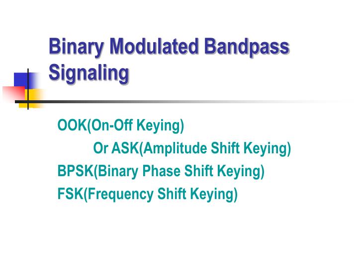
Binary Modulated Bandpass Signaling. OOK(On-Off Keying) Or ASK(Amplitude Shift Keying) BPSK(Binary Phase Shift Keying) FSK(Frequency Shift Keying). Carrier Cos(2 f c t). OOK output A c m(t)Cos(2 f c t). Message m(t). Message. 1 0 1 0 1 0 1. Unipolar Modulation.

E N D
Binary Modulated Bandpass Signaling OOK(On-Off Keying) Or ASK(Amplitude Shift Keying) BPSK(Binary Phase Shift Keying) FSK(Frequency Shift Keying)
Carrier Cos(2fct) OOK output Acm(t)Cos(2fct) Message m(t) Message 1 0 1 0 1 0 1 Unipolar Modulation Bipolar Modulation OOK output OOK(On-Off Keying) • Also known as ASK(Amplitude Shift Keying)
fc 2R = 2/Tb OOK(On-Off Keying) • OOK signal in time domain • PSD(Power Spectral Density) • Conventional AM type
Binary output OOK in Envelope Detector Binary output OOK in LPF Detection of OOK • Noncoherent Detection • Coherent Detection with Low Pass Filter
Sample & Hold OOK in Binary Out VT Clock From Bit sync logic From PLL Correlator output VT Comparator input Binary output Detection of OOK • Coherent Detection with Correlator • Optimum Receiver
Detection of OOK • Choosing the detector • Optimum coherent detector • Best noise performance • More costly • Noncoherent detector • More error rate • Less costly • Trade-off between • Cost / Noise Performance
Message: m(t) Carrier:Cos(2fct) BPSK output AcCos(2fct+kpm(t)) -90 Phase shift Message 1 0 1 0 1 0 1 Unipolar Modulation Bipolar Modulation BPSK output BPSK(Binary Phase Shift Keying) • Generation
Pilot term Data term BPSK • Signals in time domain • Since m(t) = 1 • If kp is small • Then little power in data term, most power in pilot term • To maximized performance (low Pe) • Optimum case : kp = /2
If kp /2 Pilot exists fc 2R = 2/Tb BPSK • PSD of optimum BPSK • Equivalent to DSB
Binary output BPSK in LPF From PLL if pilot exist Costas Loop or Squaring Loop if no pilot exist Detection of BPSK • Coherent Detector with Low Pass Filter • To remove Half cycle (180 phase) ambiguity • DPSK(Differential PSK) is used
Correlator output VT=0 Comparator input Binary output Detection of BPSK • Optimum Detector Sample & Hold BPSK in Binary Out Clock From Bit sync logic VT=0 From PLL, Costas loop
DPSK(Differential PSK) • DPSK = Differential Coding + BPSK • DPSK is often used instead of BPSK because it does not require carrier synchronizer circuits • Differential Coding • Differential Encoding : • Differential Decoding :
Data in Delay Tb Line Encoder Channel Line Decoder Differential Encoder Data out Delay Tb Differential Decoder Differential Coding • Differential Encoding/Decoding
Encoding Input sequence dn 1 1 0 1 0 0 1 Encoding sequence en 1 0 1 1 0 0 0 1 Reference digit Decoding (with correct channel polarity) received sequence en 1 0 1 1 0 0 0 1 Encoding sequence dn 1 1 0 1 0 0 1 Decoding (with inverted channel polarity) received sequence en0 1 0 0 1 1 1 0 Encoding sequence dn 1 1 0 1 0 0 1 Example of Differential Coding
BPSK in LPF Binary Out Delay Tb BPSK in Correlator Or Matched filter Binary Out Delay Tb Detection of DPSK • Not requires carrier synchronizer circuits • Partially Coherent Detector • Optimum Detector
Message: m(t) Cos(2f1t) FSK output AcCos(2f1t+1) or AcCos(2f2t+2) Osc. f1 Cos(2f2t) Osc. f2 Frequency Modulator fc FSK output Message: m(t) FSK(Frequency Shift Keying) • Generation • Discontinuous FSK • Continuous FSK
Message 1 0 1 0 1 0 1 Unipolar Modulation Bipolar Modulation FSK output (Discontinuous) FSK output (Continuous) Mark(binary 1) frequency: f1 Space(binary 0) frequency: f2 FSK • Waveforms in FSK
FSK in Frequency Detector Binary Output FSK in LPF Binary Output Cos(2f1t) LPF Cos(2f2t) Detection of FSK • Noncoherent Detector • Coherent Detector with Low Pass Filter
detector Correlator Or Matched Filter FSK in Binary Output Cos(2f1t) Correlator Or Matched Filter Cos(2f2t) Detection of FSK • Optimum Detector
Digital data Dial up phone line Computer FSK modem (Originate) f1 = 2225Hz f2 = 2025Hz PSTN Computer Center FSK modem (Answer) f1 = 1270Hz f2 = 1070Hz Bell-Type 103 FSK Modem • FSK with speed of 300 bps • QAM is used for higher data rate