Download
1 / 25
250 likes | 264 Views
Learn about timers, interrupts, and GPIO in embedded systems. Understand time components, timers, and handling interrupts in MQX environment with examples. Explore GPIO drivers and controls for input/output pins.

E N D
LAB 12: Timer and Interrupt Chung-Ta King National Tsing Hua University CS 4101 Introduction to Embedded Systems
Introduction • In this lab, we will learn • Timer, interrupt, and GPIO of MQX • To use timer and GPIO interrupt
MQX Time • Kept as a 64-bit count of the number of tick interrupts since the application started to run • Time component: • Elapsed time: amount of time since MQX started • Absolute time: time since the reference date of 0:00:00.000 January 1, 1970 • Time unit: • Seconds/milliseconds (second/millisecond time) • Ticks (tick time) • Date (date time and extended date time)
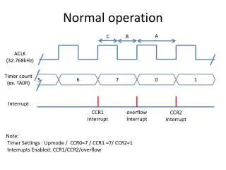
Timers • An application can use timers: • To cause notification function to run at specific time • When MQX creates the timer component, it starts Timer task, which maintains timers and application-defined notification functions. When a timer expires, Timer task calls the appropriate notification function. • To communicate that a time period has expired • A task can start a timer at a specific time or at some specific time after the current time • Types of timers: • One-shot timer: expire once • Periodic timer: expire repeatedly at specified interval
Example of Timers • Simulate a LED being turned on and off every second using printf() • One timer turns the LED on, and another turns it off. • Each timer has a period of 2 seconds with an offset of 1 second between them. • Task runs for 6 seconds.
Timer Example Explained • Data structure of ticks: typedef struct mqx_tick_struct{ _mqx_uint TICKS[MQX_NUM_TICK_FIELDS]; uint_32 HW_TICKS; } MQX_TICK_STRUCT; • _time_init_ticks() • Initializes a tick-time structure with a specified number of ticks • _time_get_elapsed_ticks() • Gets the tick time that has elapsed, since the application started on this processor
Timer Example Explained • _timer_start_periodic_at_ticks • Starts a periodic timer at a specific time (in tick) _timer_id _timer_start_periodic_at_ticks( void (_CODE_PTR_ notification_function) (_timer_id id, pointer data_ptr, MQX_TICK_STRUCT_PTR tick_time_ptr), pointer notification_data_ptr, _mqx_uint mode, MQX_TICK_STRUCT_PTR tick_time_start_ptr, MQX_TICK_STRUCT_PTR tick_time_wait_ptr)
Handling Interrupts • An MQX ISR is not a task. It is a small routine that reacts to hardware interrupts or exceptions • When MQX calls an ISR, it passes a parameter that application defines, when application installs the ISR • There is a kernel ISR (_int_kernel_isr()) that runs before any other ISR: • It saves the context of the active task. • It switches to the interrupt stack. • It calls the appropriate ISR. • After the ISR has returned, it restores the context of the highest-priority ready task
Initializing Interrupt Handling • When the MQX starts, it initializes its ISR table, which has an entry for each interrupt number: • A pointer to the ISR to call. • Data to pass as a parameter to the ISR. • A pointer to an exception handler for that ISR. • Initially, the ISR for each entry is the default ISR _int_default_isr(), which blocks the active task. • An application can replace an ISR with an application-defined, interrupt-specific ISR using _int_install_isr()
Example of Interrupts (1/3) • Install an ISR to chain it to the previous ISR, which is the BSP-provided periodic timer ISR.
Interrupt Example Explained • _int_get_isr • Get the current ISR for the vector number • _int_get_isr_data • Get the data associated with the vector number • _int_install_isr • vector: vector number of the interrupt • isr_ptr:pointer to the ISR • isr_data:pointer to the data to be passed as the first parameter to the ISR
GPIO Driver • GPIO drivers create a hardware abstraction layer for application to use input or output pins. • To access GPIO pins, need to open GPIO device with a parameter specifying set of pins to be used, e.g., file = fopen(“gpio:input”, &pin_table); • The pin_tableis an array of GPIO_PIN_STRUCTended with GPIO_LIST_END. • A pin is described as: <port_name>|<pin_#>|<additional_flags>
GPIO Driver • Example of pin_tableinitialization structure: const GPIO_PIN_STRUCT pin_table[] = { GPIO_PORT_NQ | GPIO_PIN5 | GPIO_PIN_IRQ, GPIO_PORT_TC | GPIO_PIN3, GPIO_LIST_END }; • The GPIO device driver provides these services: API Calls _io_fopen() _gpio_open() _io_fclose() _gpio_close() _io_ioctl() _gpio_ioctl()
Some GPIO Controls • GPIO_IOCTL_ADD_PINS • Adds pins to the file. The parameter is GPIO_PIN_STRUCT array. • GPIO_IOCTL_WRITE_LOG1 • Sets output pins. If the parameter is GPIO_PIN_STRUCT array, the driver sets all pins specified • GPIO_IOCTL_WRITE • Sets or clears output pins according to GPIO_PIN_STRUCT array. • GPIO_IOCTL_READ • Reads status of input pins and update the GPIO_PIN_STRUCT array. • GPIO_IOCTL_SET_IRQ_FUNCTION • Sets the callback function which is invoked for any IRQ event coming from any file pin. • GPIO_IOCTL_ENABLE_IRQ • Enables IRQ functionality for all IRQ pins in the file.
Example of Using IOCTL Command • Set all pins attached to the file: ioctl(file, GPIO_IOCTL_WRITE_LOG1, NULL); • Read pin status to read_pin_table: if(ioctl(file, GPIO_IOCTL_READ, &read_pin_table) == IO_OK) { if((read_pin_table[0]& GPIO_PIN_STATUS) == GPIO_PIN_STATUS_1) {// first pin in the table is set} }
Basic Lab • When pushing a button, use button interrupt to create a new countdown task which uses timer interrupt to count from 5 to 0 • In timer interrupt function, print the tid and countdown number.
Bonus • Print a 5*5 map on your PC screen. When you push the button, randomly place a bomb on the map and the bomb will count down from 5 to 0. • Use a clock to track the game time that counts from 60 to 0. When the timer expires, then the game over.