Download
1 / 24
250 likes | 407 Views
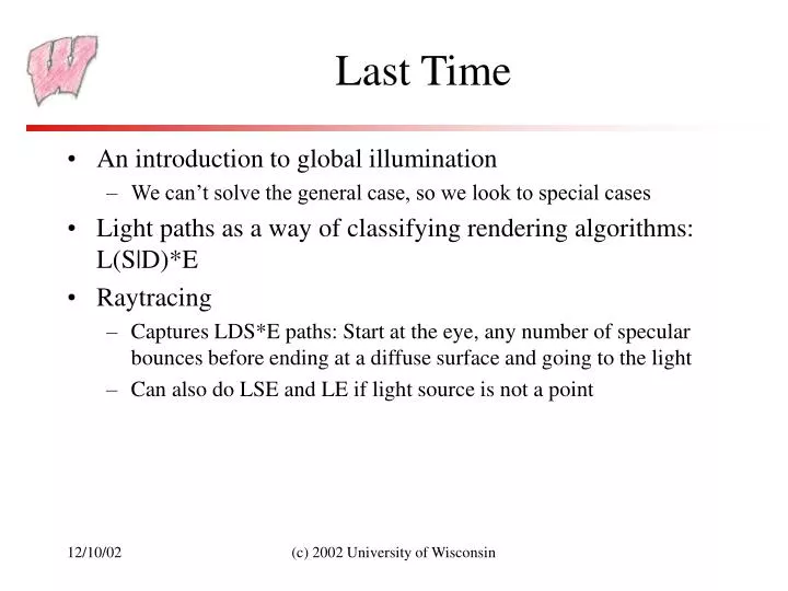
Last Time. An introduction to global illumination We can’t solve the general case, so we look to special cases Light paths as a way of classifying rendering algorithms: L(S|D)*E Raytracing

E N D
Last Time • An introduction to global illumination • We can’t solve the general case, so we look to special cases • Light paths as a way of classifying rendering algorithms: L(S|D)*E • Raytracing • Captures LDS*E paths: Start at the eye, any number of specular bounces before ending at a diffuse surface and going to the light • Can also do LSE and LE if light source is not a point (c) 2002 University of Wisconsin
Today • A bit more on ray-tracing • Bi-directional ray-tracing • Radiosity • Take home point: What algorithms do what sort of light paths, and what assumptions do they make (c) 2002 University of Wisconsin
Mapping Techniques • Raytracing provides a wealth of information about the visible surface point: • Position, normal, texture coordinates, illuminants, color… • Raytracing also has great flexibility • Every point is computed independently, so effects can easily be applied on a per-pixel basis • Reflection and transmission and shadow rays can be manipulated for various effects • Even the intersection point can be modified (c) 2002 University of Wisconsin
Bump Mapping Examples (c) 2002 University of Wisconsin
Displacement Mapping • Bump mapping changes only the normal, not the intersection point • Silhouettes will not show bumps, even though shading does • Displacement mapping actually shifts the intersection point according to a map • Gives bump map effects and also correct silhouettes and self shadowing, if implemented fully (c) 2002 University of Wisconsin
From RmanNotes http://www.cgrg.ohio-state.edu/~smay/RManNotes/index.html (c) 2002 University of Wisconsin
Soft Shadows • Light sources that extend over an area (area light sources) should cast soft-edged shadows • Some points see all the light - fully illuminated • Some points see none of the light source - the umbra • Some points see part of the light source - the penumbra • To ray-trace area light sources, cast multiple shadow rays • Each one to a different point on the light source • Weigh illumination by the number that get through (c) 2002 University of Wisconsin
Soft Shadows Penumbra Umbra Penumbra (c) 2002 University of Wisconsin
Soft Shadows All shadow rays go through No shadow rays go through Some shadow rays go through (c) 2002 University of Wisconsin
Ray-Tracing and Sampling • Basic ray-tracing casts one ray through each pixel, sends one ray for each reflection, one ray for each point light, etc • This represents a single sample for each point, and for an animation, a single sample for each frame • Many important effects require more samples: • Motion blur: A photograph of a moving object smears the object across the film (longer exposure, more motion blur) • Depth of Field: Objects not located at the focal distance appear blurred when viewed through a real lens system • Rough reflections: Reflections in a rough surface appear blurred (c) 2002 University of Wisconsin
Distribution Raytracing • Distribution raytracing casts more than one ray for each sample • Originally called distributed raytracing, but the name’s confusing • How would you sample to get motion blur? • How would you sample to get rough reflections? • How would you sample to get depth of field? (c) 2002 University of Wisconsin
Distribution Raytracing • Multiple rays for each pixel, distributed in time, gives you motion blur • Object positions have to vary continuously over time • Casting multiple reflection rays at a reflective surface and averaging the results gives you rough, blurry reflections • Simulating multiple paths through the camera lens system gives you depth of field (c) 2002 University of Wisconsin
Motion Blur (c) 2002 University of Wisconsin
Distribution Raytracing Depth of Field From Alan Watt, “3D Computer Graphics” (c) 2002 University of Wisconsin
Missing Paths • Basic recursive raytracing cannot do: • LS*D+E: Light bouncing off a shiny surface like a mirror and illuminating a diffuse surface • LD+E: Light bouncing off one diffuse surface to illuminate others • Basic problem: The raytracer doesn’t know where to send rays out of the diffuse surface to capture the incoming light • Also a problem for rough specular reflection • Fuzzy reflections in rough shiny objects (c) 2002 University of Wisconsin
Bi-directional Raytracing • Cast rays from the light sources out into the scene • When a ray hits a diffuse surface, accumulate some light there • Surfaces record the amount of light that hits them • Store the light in texture maps • Store the light in quadtrees • Store the light in photon maps • Cast rays from the eye out into the scene • When a ray hits a diffuse surface, look up the amount of light that hit it in the light-ray phase • What paths does it capture? • What sort of visual effects do you see? (c) 2002 University of Wisconsin
Caustics Standard raytracer: Diffuse table and blue ball, mirrors left, right and back, transparent red ball Bi-directional raytracer More rays in the light pass Note the LS*DS*E paths From Alan Watt, “3D Computer Graphics” (c) 2002 University of Wisconsin
Refraction caustic Henrik wann Jensen, http://www.gk.dtu.dk/~hwj (c) 2002 University of Wisconsin
Refraction caustics Henrik wann Jensen, http://www.gk.dtu.dk/~hwj (c) 2002 University of Wisconsin
Still Missing… • LD*E paths – Diffuse-diffuse transport • Formulated and solved with radiosity methods • L(S|D)*E paths • Solved with Monte-Carlo renderers – very very inefficient • Also solvable with multi-pass methods, but also very very inefficient, and subject to aliasing • An unsolved problem (c) 2002 University of Wisconsin
Real World LD*E Paths From Alan Watt, “3D Computer Graphics” (c) 2002 University of Wisconsin
Radiosity Assumptions • All surfaces are perfectly diffuse • Means that is doesn’t matter which way light hits or leaves a surface • Illumination is constant over a patch • Can break the world up into a discrete number of pieces • Problems at sharp illumination boundaries - shadows • Ways around these problems, but less efficient and less able to manage scene complexity • Assumptions allow us to solve for LD*E paths (c) 2002 University of Wisconsin
Radiosity Example • Color bleeding is extreme in this example • Textures are applied after solving for illumination • Some meshing artifacts are visible - note the banding around the pictures on the wall From Alan Watt, “3D Computer Graphics” (c) 2002 University of Wisconsin
Radiosity Meshing • Each patch is colored with its illumination • Note the discrete nature of the solution • The previous image was obtained by pushing color to vertices and then Gourand shading From Alan Watt, “3D Computer Graphics” (c) 2002 University of Wisconsin