Download
1 / 50
700 likes | 1.1k Views
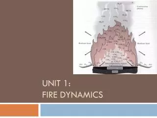
UNIT 2: INTRODUCTION TO FIRE MODELING. TERMINAL OBJECTIVE. Given two types of fire effects models, give an example of each, describe each model’s capabilities and limitations, and explain their roles in building or fire code performance-based design to include alternative materials and methods.

E N D
TERMINAL OBJECTIVE • Given two types of fire effects models, give an example of each, describe each model’s capabilities and limitations, and explain their roles in building or fire code performance-based design to include alternative materials and methods.
ENABLING OBJECTIVES The student will: • Describe the field fire model. • Describe the zone fire model.
INTRODUCTION TO COMPUTER FIRE MODELS • Use of a computer to recreate or “model” the fire environment is another tool for the investigator to use in fire scene analysis. • The recreation of the fire environment is accomplished through the use of mathematical equations. • The concept of computer fire modeling has been in existence since the 1960s.
INTRODUCTION TO COMPUTER FIRE MODELS (con.) • The need to understand and explain scientific principles relevant to fire growth, development, and flashover • Focus of fire researchers at the National Institute of Standards and Technology (NIST) since the 1970s
THE IMPACT OF COMPUTER MODELING ON FIRE RESEARCH • Used in performance-based designs because of the “ease” in which the model can replicate the fire environment • Cost and labor of the traditional methods of testing has been greatly reduced
OVERALL DEGREE OF ACCURACY • No model should be expected to be more accurate than the physical world it attempts to represent • The following slide show a comparison the results of an study conducted by the Nuclear Regulatory Commission. • Studies compared the range of predictions between the different types of models.
ACCURACY OF FIRE MODELS • NUREG 1824 Analysis
ACCURACY OF FIRE MODELS (con.) • NUREG 1824 Analysis
MODEL SENSITIVITY • A sensitivity analysis demonstrates the relative magnitude of change in output that can be expected by changing an input parameter. • Some parameter changes will result in small changes in model predictions, while others may result in large changes in the predicted values.
VARIABILITY AND UNCERTAINTY OF FIRE TEST DATA • Even under idealized test conditions, replicate tests will not provide exactly the same results. • There is also uncertainty in obtaining fire test data as a result of measurement errors and other factors.
SCIENCE BEHIND THE MODELS • Navier-Stokes – equations that mathematically describe the transport of mass, momentum,and energy in fluids • Models continually solve for these equations in the “fire environment”
FIRE MODEL TYPES • Zone: • FPETool • ASET-B • DETACT-QS • CFAST • Computational Fluid Dynamics (CFD aka Field): • Fire Dynamics Simulator (FDS)
ZONE MODELS • Zone models work on the concept that the compartment is divided into two distinctive zones: upper (hot layer) and lower (cool) layer.
ZONE MODEL FEATURES • Assume uniform temperature and gas in a zone
OVERVIEW OF ZONE MODELS • ASET-B (Available Safe Egress Time-BASIC) • DETACT-QS (DETector ACTuation-Quasi Steady) • DETACT-T2 (DETector ACTuation-Time squared) • FASTLite • FIRST (FIRe Simulation Technique) • FPETool • CFAST (Consolidated Fire and Smoke Transport)
FIRE MODELING - INPUT • Domain size • Grid resolution (some models) • Computational time • Physical geometry • Material properties • Initial conditions • Boundary conditions • Instruments • Output
ZONE MODEL LIMITATIONS • Interior finish flame spread not included • Ignitability from smoldering combustion not modeled • HRR is an input • Fire suppression not fully modeled (first sprinkler only, affects only the HRR)
SOME LIMITATIONS • Compartments must have smooth, flat ceilings (defined in NFPA 72) • Maximum size of compartments is limited • Smoke detector (DETACT) is based on temperature rise over ambient (41ºF, 5ºC) • Location of slice files is fixed
SOME LIMITATIONS (con.) • Location of detectors and sprinklers does not visualize in Smokeview • Vent status (open, closed) can only be changed one time during a simulation • Slice files only show temperature • Radiant heat transfer is limited by a default amount
OTHER ISSUES • Walls thicknesses are not a data point • Concern is with surface material properties • Any openings to the exterior are considered open to the world
SMOKEVIEW • Loads along with CFAST • Provides a visualization of the simulation • 3-D visual output of the “fire”
FIRE DYNAMICS SIMULATOR AKA FDS • Current version being used is 5.4 • Version 6 is under development • Version 4 and 5 are not directly compatible • Also includes Smokeview
CFD (FIELD) MODELS • Divide space into small rectangular cells • Compute: • Density • Velocity • Temperature • Pressure
CFD MODELS • Compute gas species concentrations in each cell • Compute gas movement based on laws of mass, momentum, and energy • Fire suppression (sprinklers) can be modeled • Smoke detector (ion and photo) operation can be modeled
SMOKEVIEW Smokeview
Smokeview SMOKEVIEW
FIRE MODELING - INPUT • Domain size • Physical space in which you are going to model (x,y,z)
COORDINATE SYSTEM USED • Location of “obstructions” is entered using the x,y,z coordinates in a sextuplet format • x1,x2,y1,y2,z1,z2 or • xmin,xmax,ymin,ymax,zmin, zmaz • All are referenced from 0,0,0 • Must be entered in metric (meters)
DATA INPUT • Lines of “code” written in notepad format • Commercially produced software from Pyrosym • Excel spreadsheets developed by the engineering staff of Montgomery County (MD) Fire Rescue Services
JUST A LITTLE “CODE” &OBST XB=0.00, 11.58, 0.00, 0.1524, 0.00, 2.44 SURF_ID='GYPSUM BOARD' PERMIT_HOLE=.TRUE. SAWTOOTH=.TRUE. THICKEN=.FALSE./ Wall &OBST XB=0.00, 11.58, 7.62, 7.77, 0.00, 2.44 SURF_ID='GYPSUM BOARD' PERMIT_HOLE=.TRUE. SAWTOOTH=.TRUE. THICKEN=.FALSE./ Wall &OBST XB=11.58, 11.73, 0.00, 7.77, 0.00, 2.44 SURF_ID='GYPSUM BOARD' PERMIT_HOLE=.TRUE. SAWTOOTH=.TRUE. THICKEN=.FALSE./ Wall &OBST XB=0.00, 0.1524, 0.1524, 7.62, 0.00, 2.44 SURF_ID='GYPSUM BOARD' PERMIT_HOLE=.TRUE. SAWTOOTH=.TRUE. THICKEN=.FALSE./ Wall &OBST XB=3.96, 4.11, 4.11, 7.62, 0.00, 2.44 SURF_ID='GYPSUM BOARD' PERMIT_HOLE=.TRUE. SAWTOOTH=.TRUE. THICKEN=.FALSE./ Wall &OBST XB=3.96, 7.32, 4.11, 4.27, 0.00, 2.44 SURF_ID='GYPSUM BOARD' PERMIT_HOLE=.TRUE. SAWTOOTH=.TRUE. THICKEN=.FALSE./ Wall &OBST XB=5.79, 5.94, 0.1524, 3.35, 0.00, 2.44 SURF_ID='GYPSUM BOARD' PERMIT_HOLE=.TRUE. SAWTOOTH=.TRUE. THICKEN=.FALSE./ Wall &OBST XB=8.08, 11.58, 4.11, 4.27, 0.00, 2.44 SURF_ID='GYPSUM BOARD' PERMIT_HOLE=.TRUE. SAWTOOTH=.TRUE. THICKEN=.FALSE./ Wall
FIRE MODELING - INPUT • Grid resolution • Determines how often within the domain it will calculate variables, such as, temperature, pressure, and velocity • Defines the number of grid cells
FIRE MODELING - INPUT • Computational time • How much time do you want to simulate? • This is not the amount of time that it will take for the computer to complete the simulation!
FIRE MODELING – INPUT (con.) • Material properties • The surface of the physical geometryjust defined • Initial conditions • Define what is going on at time = 0 • Temperature, velocity, density, conductivity, specific heat, pressure, and other conditions when simulation starts
FIRE MODELING – INPUT (con.) • Boundary conditions • Regulates conditionsat domain edges • Allows air to move in and out freely basedon physics
DEMONSTRATION: CHOICE OF BOUNDARY • Consider an experiment • 3x3x3m box inside a laboratory • Box has “hot” vertical wall to create natural convection • Measured temperature and airflow within the box
DEMONSTRATION: CHOICE OF BOUNDARY (con.) • Now, simulate the 3x3x3m box with FDS • Choice of boundary outside of the • Building containing the laboratory • Laboratory • Box • Two boundaries selected for simulation • Set computational boundaryat box exterior • Extend computational boundary so itis larger than the box exterior and includes someof the lab space
FIRE MODELING - OUTPUT • Instruments and output • Instruments, such as, thermocouples, smoke detectors, heat detectors • “Thermocouples” are used for various purposes in FDS • Necessary to model what values to output and in what format
Fire Scenarios • A specific set of conditions that define the development of fire, the spread of combustion products throughout a building or portion of a building, the reactions of people to fire, and the effects of combustion products.
Design Fires • Fire scenarios are those that are used for the evaluation of a proposed design. • All stakeholders in a performance-based design must agree on the fire and design fire scenarios. • Fire models are used to evaluate the effects of the design fires on fire and life safety issues
SUMMARY • The concept of computer fire modeling has been in existence since the 1960s. • NIST. • Classifications of enclosure fire models: probabilistic models and deterministic models. • Deterministic models can be divided into two separate categories: field models and zone models.
SUMMARY (con.) • Zone models work on the concept that the compartment is divided into two distinctive zones: upper (hot layer) and lower (cool) layer. • Field models are the newest and most sophisticated of all deterministic models. They rely upon computational fluid dynamics.