Download
1 / 22
220 likes | 338 Views
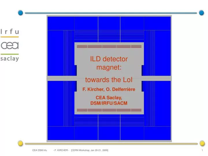
ILD detector magnet: towards the LoI F. Kircher, O. Delferrière CEA Saclay, DSM/IRFU/SACM. Summary. Introduction Version ILD-V3 Saclay for the magnet configuration 1.1 Parameter list 1.2 Coil and yoke design 1.3 Main outputs 1.4 Comparison CMS-ILD Some other points

E N D
ILD detector magnet: towards the LoI F. Kircher, O. Delferrière CEA Saclay, DSM/IRFU/SACM - F. KIRCHER - [CERN Workshop, Jan 20-21, 2009]
Summary Introduction • Version ILD-V3 Saclay for the magnet configuration 1.1 Parameter list 1.2 Coil and yoke design 1.3 Main outputs 1.4 Comparison CMS-ILD • Some other points • 1 Modules with correction current 2.2 Anti DiD coil design Conclusions - F. KIRCHER - [CERN Workshop, Jan 20-21, 2009]
Summary Introduction • Version ILD-V3 Saclay for the magnet configuration 1.1 Parameter list 1.2 Coil and yoke design 1.3 Main outputs 1.4 Comparison CMS-ILD • Some other points • 1 Modules with correction current 2.2 Anti DiD coil design Conclusions - F. KIRCHER - [CERN Workshop, Jan 20-21, 2009]
Introduction (1) . Detector concept ILD = unification of GLD and LDC projects . Main participants in the magnet effort . Japanese team (Yasuhiro Sugimoto) : ILD-G3 version (magnetic design, end cap opening) . Saclay team (O. Delférrière. F. Kircher) ILD-Vn (n=1,3 up to now) Saclay version (magnetic design) . DESY team (Uwe Schneekloth) : iron yoke design and B field calculations (see pm presentation) . Brett Parker (BNL) : anti-DID design - F. KIRCHER - [CERN Workshop, Jan 20-21, 2009]
Introduction (2) As magnet parameters are roughly the same, theILD magnet concept is based on CMS magnet with two extra requests: . High integral field homogeneity in the TPC volume . Lower fringing field (push-pull operation) - F. KIRCHER - [CERN Workshop, Jan 20-21, 2009]
Summary Introduction • Version ILD-V3 Saclay for the magnet configuration 1.1 Parameter list 1.2 Coil and yoke design 1.3 Main outputs 1.4 Comparison CMS-ILD • Some other points • 1 Modules with correction current 2.2 Anti DiD coil design Conclusions - F. KIRCHER - [CERN Workshop, Jan 20-21, 2009]
Version ILD-V3 Saclay: parameter list • Parameters used for ILD detector magnet Bodesign = 4 T (3.5 T field for operation) Rint cryostat = 3.44 m Rint coil = 3.59 m Rext coil = 3.94 m Rext cryostat = 4.19 m L coil = 7.35 m Bext≤ 100 G @ z=10 m from I.P. and ≤ 50 G @ R=15 m in the radial direction Integral of field homogeneity within the TPC volume ≤ 10 mm • This talk will report mainly on Saclay’s results - F. KIRCHER - [CERN Workshop, Jan 20-21, 2009]
Versions ILD-V3 Saclay : generalities • Magnet = Coil + iron yoke (barrel + end-caps) • Coil • 5 modules (2 different lengths) • 4 layers in each module • correction current in some parts of the coil to adjust the field homogeneity • Yoke configuration: • as described by Catherine on January 8 2009 • 30 mm gaps have been included in the ‘bulk part’ of the barrel and endcap yokes for engineering reasons • In some calculations, a packing factor has been introduced to simulate the filling of the gaps with iron • For all cases: 2D calculations (cylindrical symetry) - F. KIRCHER - [CERN Workshop, Jan 20-21, 2009]
Versions ILD-V3 Saclay : yoke R Barrel Yoke Yoke Back EC 9 layers of muons chambers+ 1 between cryo and Barrel yoke Coil+ cryo 7110 5610 Yoke front EC+ 10 muons 3 * 30 mm gap included in the ‘bulk parts ‘ of the barrel yoke and yoke back end caps 5510 5510 4340 Hcal EC FSP z 4022 Thickness of 10 layers of muon chambers : =10(100Fe+30 RPC or scin.) =1300 7190 - F. KIRCHER - [CERN Workshop, Jan 20-21, 2009]
Version ILD-V3 Saclay: field homogeneity • Request - homogeneous field in the volume of the TPC: z max l (R) =∫ (Br (R) / Bz (R) dz ≤ 10 mm 0 within the TPC volume: z max = 2.25 m and R = 0 to R max = 1.8 m - the field homogeneity is ajusted with a FSP (Field Shaping Plate) and correction currents in some places of the coil. No more iron nose, as in the previous LDC yoke design, is used to adjust the homogeneity - F. KIRCHER - [CERN Workshop, Jan 20-21, 2009]
Version ILD-V3 Saclay: main outputs Electrical parameters (4 T) Inom (kA) 18.1 Eng. J (A/mm2) 11.0 (for Inom) Icor (kA) 21.5 (3 layers * 2 modules) Stored energy (GJ) 2.05 Ws density (kJ/kg) 12.4 Integral homogeneity in TPC volume (mm) ≤ 10 Yoke dimensions Rout barel yoke (mm) 7 110 Zout endcap yoke (mm) 7 190 Stray field (no gap filling) Bext = 225 G @ Z = 10 m from I.P. and 4 T Bext = 100 G @ R = 15 m from I.P. and 3.5 T - F. KIRCHER - [CERN Workshop, Jan 20-21, 2009]
Version ILD-V3 Saclay: magnet configuration ILD-V3 SACLAY @3.5 Tesla - F. KIRCHER - [CERN Workshop, Jan 20-21, 2009]
Version ILD-V3 Saclay: coil configuration 3.5 T 4. T - F. KIRCHER - [CERN Workshop, Jan 20-21, 2009]
Version ILD-V3 Saclay: field homogeneity (Br/Bz)dz vs r (z=0 to 2.25 m) - F. KIRCHER - [CERN Workshop, Jan 20-21, 2009]
Version ILD-V3 Saclay: maximum field @4T - F. KIRCHER - [CERN Workshop, Jan 20-21, 2009]
Version ILD-V3 Saclay: fringing field - F. KIRCHER - [CERN Workshop, Jan 20-21, 2009]
Version ILD-V3 Saclay: comparison with CMS - F. KIRCHER - [CERN Workshop, Jan 20-21, 2009]
Summary Introduction • Version ILD-V3 Saclay for the magnet configuration 1.1 Parameter list 1.2 Coil and yoke design 1.3 Main outputs 1.4 Comparison CMS-ILD • Some other points • 1 Modules with correction current 2.2 Anti DiD coil design Conclusions - F. KIRCHER - [CERN Workshop, Jan 20-21, 2009]
Modules with correction current This is one of the mainnovelty from CMS.Basic concepts: • the conductor with the extra correction current has: . the same overall dimension as the conductor with the main current, typically 80*22 mm2 without insulation (a little bit longer than the CMS conductor) . but a higher current transport capacity to work with about the same safety margin with respect to the critical current (40 strands * Ø 1.7 mm vs 32 strands * Ø 1.3 mm) • a stronger mechanical support: at least for the conductor with the extra correction current, the ratio of structural material is close to 1 (cf conductor for the ATLAS Central Solenoid developed by Akira Yamamoto et al.), vs 0.6 for CMS • in case of quench, the extra local Joule heating is absorbed by the quench-back phenomenon, much quicker than the increase of temperature of the coil, and which diffuses the uniformly the heat - F. KIRCHER - [CERN Workshop, Jan 20-21, 2009]
Anti-DID coil design The anti-DiD allows to zero the crossing angle for the outgoing beam (and pairs) behind the I.P. Brett Parker has started some conceptual design study . Two dipole coils, anti-symetric with respect to the I.P. . Proposal to wind the anti-DID coil outside the main solenoid coil (reduced field region) . Field maps (3D) do not yet include the ILD solenoid . Banti-DID~ 0.065 T - F. KIRCHER - [CERN Workshop, Jan 20-21, 2009]
Summary Introduction • Version ILD-V3 Saclay for the magnet configuration 1.1 Parameter list 1.2 Coil and yoke design 1.3 Main outputs 1.4 Comparison CMS-ILD • Some other points • 1 Modules with correction current 2.2 Anti DiD coil design Conclusions - F. KIRCHER - [CERN Workshop, Jan 20-21, 2009]
Conclusions • Magnetic calculations have been done with the LoI parameters. Solutions which meet the specifications have been found • Most of the CMS concepts can still be used. Some R&D on a conductor with a ratio of structural material close to 1 would strenghten the mechanical design of the most solicited modules • Conceptual design of the anti-DID has started, and must continue with the present detector magnet configuration • Even if some points can still evolved and/or need some more studies , the present design seems at an acceptable level of study for the LoI - F. KIRCHER - [CERN Workshop, Jan 20-21, 2009]