Download
1 / 18
200 likes | 351 Views
Distribution Capacitor Placement With Distributed Generation Concerning Voltage Drop Reduction. Dr. Adly A. Girgis. Thomas M. Haire. Clemson University Clemson, SC, USA March 13, 2002. Background Information Procedure and System PQ Solution PV Solution Solution Comparison Conclusion.

E N D
Distribution Capacitor Placement With Distributed Generation Concerning Voltage Drop Reduction Dr. Adly A. Girgis Thomas M. Haire Clemson University Clemson, SC, USA March 13, 2002
Background Information Procedure and System PQ Solution PV Solution Solution Comparison Conclusion Topics
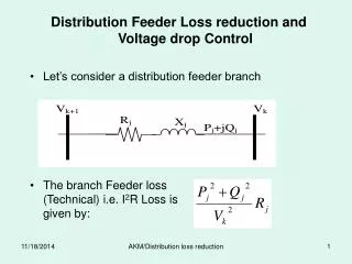
Sizing and placement standard “two-thirds rule.” A capacitor may be placed two-thirds the length of the line and may be two-thirds the size of the reactive load. Does not hold for economic consideration. This paper desires to make the voltage profile as flat as possible. Background
“Two-Thirds Rule” Where, xi distance from substation to ith capacitor n number of capacitors Ici capacitor load size (Amps or VARs) a 1, to maximize peak power loss reduction Is reactive load (Amps or VARs)
Analyze using Newton-Raphson LoadFlow PQ Solution Specify generator real and reactive power. Allow generator voltage to float. Design capacitors for constant generator power factors of 1, 0.9, 0.8. Capacitors placed and sized according to “Two-Thirds Rule.” Procedure
PV Solution Specify generator real power and voltage. Allow generator reactive power to float between 0.8 and 1. Design capacitors for estimated generator power factors of 1, 0.9, 0.8. Capacitors placed and sized according to “Two-Thirds Rule.” Procedure (cont.)
System Studied • 300 A circuit • (From observed conditions) • Zone 1, 6 mi, 4.374 MW, evenly distributed • Zone 2, 0.75 mi, 1.458 MW, evenly distributed • Power factor is 0.9 lagging. • Wire • 477 ACSR, 18/1 str. • DG • 2 Natural gas engines • 1.062 MW each
The more reactive power produced by the DG, the less voltage drop for any given number of capacitors. Excluding unity power factor at all loads. Voltage Support from both real and reactive power flowing from both directions. In practice, design generator settings and capacitor placement for DG producing maximum reactive power. Voltage Conclusions
Real and reactive power consumed by the wires is the least when all loads have capacitors and DG is operated at unity power factor. This formation will produce the least current flowing in the wires. Power Reduction Conclusions
Best profile is a result of designing the capacitors as if no DG was present. This would be a design for the DG power factor to be 1; however, the DG will not operate at unity power factor. In practice, use the “Two-Thirds Rule” as normal and let the DG chase the power factor of the system. Voltage Conclusions
The real and reactive power loss decreases as the number of capacitors increases. Most graphs show no true trend to the change in power as a result of design changes related to different DG power factors. In designs other than unity power factor, the load flow had difficulties finding a solution without lowering the DG voltage. Power Reduction Conclusions
The PV solution provided the better solution for voltage reduction. This results from not forcing any source in the system to supply a specific power. In these tests, the DG operated near the low power factor setting as in the PQ solution. Solution Comparison
The more reactive power produced by the generator, the flatter the voltage profile. If the real and reactive power from the generator are kept constant, design the capacitors for max. reactive power from the generator. If the voltage and real power are to be kept constant, design the capacitors as if the DG does not exist. Then allow DG to “chase” the system reactive power. Conclusions
Questions? Thank You! Thomas M. Haire thaire@clemson.edu (864) 656-7219