Download
1 / 42
640 likes | 2.67k Views
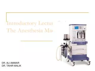
4. The anesthesia machine Morgan anesthesia. 마취통증의학과 1 년 노지성. Introduction. Modern anesthesia machines extremely sophisticated incorporating many built-in safety features & devices breathing circuit, monitors, mechnical ventilator

E N D
4. The anesthesia machineMorgan anesthesia 마취통증의학과 1년 노지성 경희의료원 마취통증의학과
Introduction • Modern anesthesia machines • extremely sophisticated • incorporating many built-in safety features & devices • breathing circuit, monitors, mechnical ventilator • microprocessors (enhance, integrate & monitor all components) ==> Anesthesia workstation • 모든 장비에 관련된 사고 중 잘못된 사용에 의한 것이 장비 자체의 결함에 의한 것 보다 3배 가량 많음 : 장비에 친숙하지 못하거나 기능 점검 실패에 의함 -> breathing circuit was the most common single source of injury
Overview • Basic form for anes machine : gas supply로부터 medical gas 받음 -> 원하는 가스의 압력을 줄여 flow control함 -> 흡입마취제를 기화시켜 final gas mixture 만듦 -> gas를 breathing circuit으로 전달 • Mechanical ventilator는 spontaneous or manual(bag) ventilation을 위해 끌 수 있음
Gas supply • gas inlet for oxygen nitrous oxide, and air • Pipeline inlets • DISS(diameter-index safety system) : color coded, noninterchangeable • filter : trap debris from the wall supply • one-way check valve : prevents retrograde flow • oxygen(pneumatic) power outlet : to drive the ventilator, an auxiliary oxygen flowmeter • Cylinder inlets • the yoke assemblies : pin index safety system : index pins, washer, gas filter, check valve 포함 • 대개 pipeline failure시 back-up supply용으로 사용 • Bourdon pressure gauge : cylinder pressure 측정 : gas pr. 가해지면 flexible tube straightened ->move a needle pointer
Flow control circuits(1) • Pressure regulators • pipeline의 압력은 거의 일정하지만 cylinder의 압력은 일정치 않아 flow control이 어려움 • pressure regulator를 통해 cylinder gas pressure를 flow valve 이전에 45-47 psig까지 낮춤(29psig=2040mmHg) • high-pressure relief valve : 공급되는 압력이 기계의 최대안전한계보다 높을 경우(95-110 psig) 열림 ; cylinder의 regulator failure시 • 일부 기계(Datex-Ohmeda)의 경우 two-stage pressure regulation을 통해 pipeline과 cylinder pressure를 모두 감소시킴 • oxygen은 20psig로, N2O는 38psig로 감소시킴 • oxygen/nitrous oxide flow linkage 의 proper functioning에 중요
Flow control circuits(2) • Oxygen supply failure protection devices • oxygen은 직접 flow control valve로 연결되지만, N2O, air등 다른 gas는 자신의 flow control valve에 도달하기 전에 safety device를 먼저 거쳐야 함 • 이러한 장비는 oxygen pressure가 충분할 경우에만 다른 gas flow를 허가하여 oxygen supply failure시의 hypoxic mixture의 전달을 막아줌 • 따라서 oxygen from common inlet pathway 은 oxygen flow control valve를 제공할뿐 아니라, safety device, oxygen flush valve, ventilator power outlet의 압력을 일정하게 유지하는데 사용됨 • 일부 모델(Datex-Ohmeda Excel)에서는 piloting pressure line이 한계 이하(20psig)로 떨어지면 다른 모든 gas의 valve가 닫힘 • proportioning safety device (oxygen failure protection device or balance regulator) : 지정된 minimum oxygen pressure 이하에서 N2O등 모든 gas flow 차단 • 모든 기계에는 oxygen supply low-pressure sensor가 있어 gas whistle or electric alarm을 작동시킬 수 있음
Flow control circuits(3) • Flow valves and meters • 안전하게 감압된 gas는 flow-control valve를 통과하여 flowmeter를 지나 다른 gas들과 섞인 후 active vaporizer로 들어가 machine's common gas outlet으로 나감 • flow valve보다 proximal쪽의 gas line을 high-pressure circuit, flow valve와 common gas outlet 사이를 low-pressure circuit이라 함 • flow control valve을 반 시계방향으로 돌리면 needle valve가 열림 • Stops in the full-off and full-on positions prevent valve damage
Flow control circuits(4) • flowmeter • constant-pressure variable-orifice flowmeter • indicator로 ball, bobbin, float가 쓰임 • 바닥쪽의 직경은 작아서 low gas flow도 float를 들어올리기에 충분한 압력 생성 • gas와 tube's wall의 마찰을 줄이기 위해 float는 지속적으로 회전하여 항상 tube 중심에 있게 됨 • flowmeter malfuction 원인: dirt in the flow tube, vertical tube, misalignment, sticking or concealment of a float at the top of a tube • oxygen flow meter이하에서 gas가 샐 경우에 대비하여 항상 oxygen flow meter는 다른 것보다 downstream에 위치하여야 함(vaporizer 근처에) • electronic flow control and measurement • flow restrictor에 의한 pressure drop의 양을 측정
Flow control circuits(5) • Flow valves and meters is designed to A. minimum oxygen flow • 마취기계가 켜져 있을 때 oxygen flow가 항상 최소 150mL/min 은 유지 B. oxygen/nitrous oxide ratio controller • O2와 N2O flow가 연결되어 최소 O2농도가 21-25%는 유지
Flow control circuits(5) • Vaporizers • flowmeter와 common gas outlet 사이에 위치 • 동시에 하나의 vaporizer만 작동하도록 interlocking or exclusion device있음 A. physics of vaporization • gas molecule이 벽에 부딪혀 vapor pressure 발생(온도가 높을수록 높아짐) • vaporization은 energy가 필요하며 이는 liquid의 열손실에서 충당됨 B. copper kettle measured-flow or flowmeter-controlled vaporizer로 분류됨 • copper : high specific heat, high thermal conductivity => maintain a constant temperature • carrier gas가 vaporizer로 들어오면 anesthetic liquid를 통과하며 vapor로 포화 • liquid anesthetic 1mL = 200mL anesthetic vapor => saturated gas는 환자에게 도달하기 전에 희석되어야 함
마취에는 7mmHg(1%=7/760) 필요 따라서 희석위해 4850ml의 gas 필요 (total gas flow=5L/min) 100ml O2가 지나면 대략 150ml의 gas가 나옴 (1/3은 halothane vapor) halothane의 vapor pr. = 243mmHg copper kettle내의 농도 = 243/760 = 32%
Vaporizers C. modern conventional vaporizers • agent specific, 온도나 flow 변화에 관계없이 일정한 농도 유지 • variable-bypass vaporizer • calibrated control knob이 열리면 gas flow의 일정량이 carrier gas로 나뉘어 vaporizing chamber로 들어감 • temperature compensation : bi-metal로 flow 조절 • flow rate의 변화는 anesthetic concentration에는 영향이 없지만 gas composition의 변화(100%O2-70%N2O)는 N2O가 volatile agent에 녹으며 ane concent.에 영향을 미칠 수 있음 • agent-specific keyed filling port가 있어 다른 agent의 주입을 막음 • pumping effect : 옛기계에서는 양압환기의 압력차에 의해 일시적으로 역류가 발생하여 마취가스량 변화 • one-way check valve(vaporizer와 O2 flush valve 사이에 위치)로 방지 • vaporizer는 주위 대기압 변화에 compensate 되도록 자동설정
Vaporizers D. electronic vaporizer • Desflurane • High volatility • vaporization의 cooling effect가 심해 일반적인 vaporizer로는 온도조절 안됨 • vaporization이 너무 잘되어 희석을 위해 high fresh gas flow 필요 • desflurane vaporizer • electrically heated to 39 C-> 2기압의 vapor pressure 발생 • Unlike a variable-bypass vaporizer, no fresh gas flows through the desflurane sump • pure desflurane vapor가 vaporizer를 나가기 전에 fresh gas mixture와 섞임 • 대기압의 변화에 따른 약제의 농도변화는 없지만, 약제의 partial pressure는 감소 -> 고지대에서는 마취과의사가 수동으로 농도를 증대시켜야 함
Common(fresh) gas outlet • multiple gas inlet, but only on common gas outlet • adding new gas of fixed and known composition to the circle system • oxygen flush valve • the flowmeters and vaporizers를 거쳐 common gas outlet에 high flow(35-55L/min) of oxygen를 제공 • real potential of lung barotrauma
The breathing circuit • circle system이 가장 흔히 쓰임 • common gas outlet에서 나오는 gas composition은 flowmeters & vaporizers에 의해 빠르고 정확하게 조절될 수 있으나 반면 breathing circuit에서의 gas composition, 즉 volatile anesthetic concentration은 여러 요인에 영향받음 ① 환자 폐에서의 anesthetic uptake ② minute ventilation ③ total fresh gas flow ④ volume of the breathing circuit ⑤ gas leaks ==> induction and emergence시에 high gas flow 사용으로 영향 줄일 수 있음 • 새로운 마취기계는 통합된 내장 호흡회로구성을 지님 f4-23 ==>장점 : misconnects, disconnects, kinks, leaks 가능성 줄임
Oxygen analyzers • 3 type : ①polarographic(Clark electrode) ②galvanic(fuel cell) : external power source가 필요 없음 ③paramagnetic • ①②는 oxygen-permeable memb.를 사이로 electrolyte gel에 sample gas와 cathode & anode electrodes가 심어진 sensors 를 이용 • ③은 초기단가는 높지만 스스로 측정이 가능하고 소모품이 없으며 반응시간이 빨라 흡기 및 호기 산소농도의 차이까지 측정할 수 있음 • 모든 O2 analyzer에는 low-level alarm이 있음 • 설치 위치는 inspiratory or expiratory limb 내에 있어야 한다.(fresh gas line엔 안됨) ; expiratory limb에선 inspiratory limb에서보다 lower oxygen partial pressure를 가짐
Spirometer • - exhaled tidal volume 측정 • 1) vane anemometer(or Wright repirometer) f4-24a • rotating vane of low mass in expiratory limb in front of the expiratory valve • Another variation: the volumeter or displacement meter 는 시간에 따라 gas의 discrete quantities 를 측정하도록 디자인 됨f4-24b • exhaled TV의 변화는 대개 ventilator setting의 변화에 의하지만, circuit leaks, disconnections, or ventilator malfunction에 의할 수도 있음 • long compliant breathing tube나 rapid respiratory rates, high airway pressure의 경우에 circuit으로 오는 gas 양과 실제로 환자에게 전달되는 양의 차이가 커짐 ==> Y-piece에서 측정하여 이러한 차이를 줄일 수 있음
Spirometer(2) • 2) hot-wire anemometer - electrically heated, fine platinum wire가 gas flow 속에 위치 - cooling effect가 전기저항의 변화를 가져와 이를 측정 - 단점 : reverse flow를 감지 못함, 발화요인 가능성 • 3) ultrasonic flow sensor - flow stream의 turbulent eddies에 의해 생긴 gas flow의 discontinuity로 측정 - 장점 : no moving parts, independence from gas density
Spirometer(3) • 4) variable-orifice flowmeter f4-24c - inspiratory & expiratory port에 각각 위치한 두개의 sensor가 내경의 차이에 따른 pressure drop을 감지 - 지나치게 응집된 sensor는 heated humidified circuit에서 사용될 때 측정에 실패하게 될 수 있음 • 5) pneumotachograph(fixed-orifice flowmeter) - parallel bundle of small-diameter tubes in chamber(Fleisch pneumotachograph) or mesh screen이 공기흐름의 약간의 저항을 만들어 이로 인한 pressure drop을 감지 - 수분축적, 온도변화에 의한 부정확성 때문에 임상이용은 제한적 => 이를 극복위한 개선품 : Y connection에 두개의 Pitot tube 사용 f-d
Circuit pressure • breathing circuit pressure는 airway pressure를 반영 => Y connection부위에서 측정시 가장 정확 • airway pressure 상승의 원인 ① pulm. compliance 악화 ② TV 증가 ③ Obxin breathing circuit, tracheal tube, or Pt's airway • airway pressure 감소의 원인 ① compliance 향상 ② TV 감소 ③ leak in the circuit
Adjustable pressure-limiting valve • fully open during spontaneous ventilation • partially closed during manual or assisted bas ventilation • fully closed되었을 경우 pressure가 점차 올라가 pulm. barotrauma and/or hemodynamic compromise 유발 • 안전장치로 압력 상한치가 70-80cmH2O로 완전히 닫히지 않게 되어있음
Humidifier(1) • absolute humidity : weight of water vapor in 1L of gas(mg/L) • relative humidity : ratio of the actual mass of water present in a volume of gas to the maximum amount of water possible at a particular temperature (예 : 37 C 100% relative humidity : absolute humidity 44mg/L, 21 C 100% humidity : 18mg/L) • gas는 상기도내에서 체온까지 덥혀지고 습도도 증가되어야 하지만 tracheal intubation이나 high fresh gas flow는 이를 bypass 함 => 하기도의 dehydration of mucosa, altered ciliary function, inspissation of secretions, atelectasis, ventilation/perfusion mismatching유발
Humidifier(2) • a. passive humidifier - condenser humidifier or heat and moisture exchanger(HME) f4-25 - do not add heat or vapor - 흡습성 물질이 호기된 습기를 잡아 흡기시 배출 - dead space 증가 소아에서 상당량의 rebreathing 초래 가능 - HME가 습기와 분비물로 지나치게 포화되면 breathing circuit이 막힐 수 있음 - effective filter역할도 가능
Humidifier(3) • ① passover humidifier • ② wick humidifier • ③ bubble-through humidifier • ④ vapor-phase humidifier • b. active humidifier • heated humidifier의 위험성 ① thermal lung injury② nosocomial infection③ circuit disconnection ④ increased airway resistance⑤ interference with flowmeter function • 소아에서 hypothermia & small tracheal tube에 dried secretion의 plugging 방지 • filter기능은 없음
Ventilators • 일부 최근 모델의 경우 ICU에서 쓰이는 ventilator와 같은 정도의 정교함과 기능을 지닌 ‘ICU-type' ventilator를 채용 • Overview • proximal airway와 alveoli 사이의 pressure gradient를 만들어 gas flow를 생성 • 예전에는 chest주위에 negative pressure를 만들었지만, 현대의 ventilator는 upper airway에 positive pressure와 gas flow를 만듦
Ventilators(2) • a. inspiratory phase ① constant-pressure generators ② constant-flow generators ③ nonconstant generators • half cycle of a sine wave를 닮은 flow pattern • airway resistance증가나 lung compliance감소가 peak inspiratory pressure의 증가를 가져오지만, flow rate는 변하지 않음
Ventilators(3) • b. transition phase from inspiration to expiration • inspiratory phase의 끝은 preset limit of time (fixed duration), set inspiratory pressure에의 도달, predetermined tidal volume 등에 의해 결정 ① time-cycled ventilators : lung compliance에 의해 TV 과 peak insp. pr. 결정 ② pressure-cycled ventilators Preset pressure에 도달되지 않으면 cycling 되지 않는 시스템. ③ volume-cycled ventilators : inspiratory duration and pressure를 변경하여 preset vol. 을 전달
Ventilators(4) • c. expiratory phase • Passive exhalation으로 airway pr.를 대기압 수준이나 정해진 PEEP 로 감소시킴 • flow out은 airway resistance와 lung compliance에 의해 결정
Ventilators(5) • d. transition phase from expiration to inspiration • preset time interval이나 change in pressure에 의함 ①volume-control mode에서는 set ventilatory rate & I:E ratio에 의해 gas flow rate & inspiratory time 결정 ②pressure-control mode에서는 inspiratory time은 set ventilator rate & I:E ratio에 의해, gas flow는 constant inspiratory pressure를 유지하는 선에서 결정
Ventilator circuit design • a. double-circuit system ventilators • bellows로부터 TV 전달 • a standing bellows • bellows는 anesthesia circuit에서 breathing bag의 역할 • 환자의 자발호흡으로 negative pr. 발생시 밖의 공기가 들어와 bellow가 collapse되도록 free breathing valve가 있음
Ventilator circuit design • b. piston ventilators • bellow대신 electrically driven piston으로 구성 • very poor lung compliance 또는 very small Pt에게도 정확한 TV 전달 가능 • piston은 volume-controlled시에는 일정한 속도로, pressure-controlled시에는 속도를 감소시키며 움직임 • negative-pressure relief valve : 음압이 발견되면 piston이 downstroke되어 심한 음압 방지
Ventilator circuit design • c. spill valve • ventilator사용시 circle system의 APL valve는 기능적으로 분리되어야 함 : bag/ventilator switch 가 있어서 bag으로 돌리면 spontaneous vent. 가 가능하게 됨 • spill valve : ventilator 자체의 pressure-relief(pop-off) valve : 흡기시 pneumatically closed : 호기시 열림
TV 상승, pulmonary compliance 감소 기도저항 상승, insp. gas flow rate 증가 Pressure and volume monitoring • peak insp. pr.: • indication of dynamic compliance • plateau pressure : • mirror of static compliance
Ventilator alarms • ’disconnect alarm’ : ① low peak inspiratory pressure ② low exhaled tidal volume ③ low exhaled CO2 • : 적은 누출이나 불완전한 circuit 분리는 위 ①②③의 약간의 감소로 알 수 있음 • 기타 alarm : ④ high peak insp. pr., ⑤ high PEEP,⑥ negative pr., ⑦ low oxygen-supply pr.
Problems associated with anesthesia ventilators • a. ventilator-fresh gas flow coupling • 흡기시에는 spill valve가 닫히면서 common gas outlet으로부터의 fresh gas flow가 TV에 추가됨 • 예를 들어 fresh gas flow 6L/min, I:E ratio 1:2, respiratory rate 10회/min ==> 각 TV에는 ventilator의 output에 200ml씩 추가됨 • 따라서 fresh gas flow가 증가하면 TV, minute ventilation, peak inspiratory pressure가 증가 • 이를 막기 위해 airway pressure와 exhaled TV을 감시하며 지나친 fresh gas flow를 피해야 함
Problems associated with anesthesia ventilators • b. excessive positive pressure • ventilator의 잘못된 setting이나 오작동, fresh gas flow coupling, 흡기 중 O2 flush 작동 등에 의해 발생 • pulmonary barotrauma 나 hemodynamic compromise 초래
Problems associated with anesthesia ventilators • c. tidal volume discrepancies • 원인 : breathing circuit compliance, gas compression, ventilator-fresh gas flow coupling, & leaks in the anesthesia machine, breathing circuit, patient's airway • 이를 감지하기 위해 spirometer는 Y connector 주위에 위치
Thanks for your attention 경희의료원 마취통증의학과
Waste-gas scavengers • NIOSH의 권고치 : OR내의 N2O는 25ppm이하, halogenated agent는 2ppm이하(N2O사용시 0.5ppm 이하) • APL valve나 spill valve로 배출되는 gas는 hose (transfer tubing)로 연결되어 scavenging interface로 연결됨 ① open interface ; 대기와 연결됨 closed interface : negative- & positive-pressure relief valve 필요 ② passive scavenging : recirculation 너머의 ventilation duct 통해 밖으로 배출 active scavenging : 병원내 vacuum system으로 연결 • 최소한 10-15L/min 이상 배출