Download
1 / 36
360 likes | 566 Views
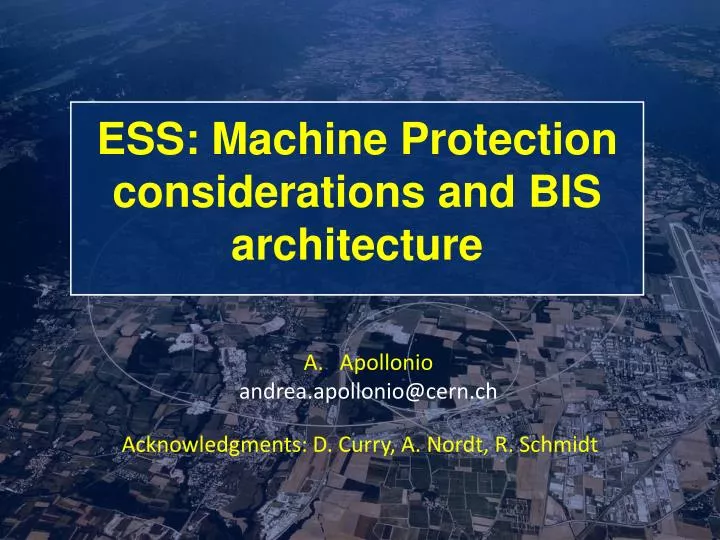
ESS : Machine Protection considerations and BIS architecture. Apollonio andrea.apollonio@cern.ch. Acknowledgments: D. Curry, A. Nordt , R. Schmidt. Outline. Introduction to ESS Linac4 Comparison ESS MPS and BIS Architecture Conclusions. Outline. Introduction to ESS

E N D
ESS: Machine Protection considerations and BIS architecture Apollonio andrea.apollonio@cern.ch Acknowledgments: D. Curry, A. Nordt, R. Schmidt
Outline • Introduction to ESS • Linac4 Comparison • ESS MPS and BIS Architecture • Conclusions
Outline • Introduction to ESS • Linac4 Comparison • ESS MPS and BIS Architecture • Conclusions
Overview • The European Spallation Source (ESS) will house the most powerful proton linac ever built. • The average beam power will be 5 MW which is five times greater than SNS. • The peak beam power will be 125 MW which is over seven times greater than SNS • ESS is located in southern Sweden adjacent to MAX-IV (A 4th generation light source) • To provide a world-class material research center for Europe Lund (Sweden) [1]
What is ESS? • ESS is a neutron spallation source for neutron scattering measurements. • Neutron scattering offers a complementary view of matter • in comparison to other probes such as x-rays from synchrotron light sources. • The scattering cross section of many elements can be much larger for neutrons than for photons. [1]
Neutron Scattering • Neutron scattering can reveal the molecular and magnetic structure and behavior of materials, such as: • Structural biology and biotechnology, magnetism and superconductivity, chemical and engineering materials, nanotechnology, complex fluids, and others X-Ray Image Neutron scattering of hydrogen in a metal organic framework Neutron radiograph of a flower corsage Neutron radiograph [1]
What is Different About ESS? Average Linac Current Output Energy Repetition Rate Pulse Length • The average proton beam power will be 5 MW • Average neutron flux is proportional to average beam power • 5 MW is five times greater than SNS beam power • The total proton energy per pulse will be 360 kJ • Beam brightness (neutrons per pulse) is proportional to total proton energy per pulse • 360 kJ is over 20 times greater than SNS total proton energy per pulse = 62.5 mA * 2 GeV * 14 Hz * 2.86 ms [1]
Outline • Introduction to ESS • Linac4 Comparison • ESS MPS and BIS Architecture • Conclusions
Linac4: Layout 45keV 3MeV 50MeV 100MeV 160MeV LEBT H-Source RFQ MEBT DTL CCDTL PIMS Transfer Line Low Energy Beam Transfer Medium Energy Beam Transfer Coupled Cell Drift Tube Linac Drift Tube Linac Pi Mode Structure Radio- Frequency Quadrupole acceleration acceleration RFQ DTL PiMS Courtesy L. Hein
Linac4 MPS: requirements • Focus of Linac4 MPS: • Availability: target >95% • Activation: above 10 MeV in case of beam losses [2] • Damage: very low risk of significant damage in case of ‘single pulse losses’ • Optimization of proton delivery to the different destinations • MPS requirements: • Highly dependable (almost same HW as LHC BIS) • Reaction time within the same pulse (<400us) • Allow for flexible operation (SIS + External Conditions) • MPS requirements during commissioning depend on: • Energy reached • Bunch intensity • Users availability
BIS ACTIONS • ‘psb ejection’ Master bic • disable the extraction kickers • magnet current acquisitions at extraction time surveyed in addition via the SIS • ‘choppers’ Master bic: • Action on the Pre-chopper at 45 keV • For redundancy, action on the chopperat 3 MeV • In addition, the PSB RF is disabled in case some beam still reaches the PSB • ‘Source RF’ Master bic: • Action on the Source RF in order to inhibit the RF voltage • For redundancy, action on the Pre-chopper in order to deflect the beam at 45 keV • To preserve the Linac4 Source stability, it is always better to act on the choppers to stop the beam, when possible
Outline • Introduction to ESS • Linac4 Comparison • ESS MPS and BIS Architecture • Conclusions
ESS: Target Tungsten target with rotating wheel 33 sectors with cooling channels (Helium) Synchronized to 14 Hz Target Monolith r=6m, h=10m He flow around slices Wheel Proton Beam Window 2mm gap Beam Ports Angular sectors Courtesy A. Nordt
2 Weeks at ESS: MPS Activities • A risk analysis on a system basis had already been carried out • Several meetings per day with different system experts to investigate possible failures and failure effects • Use of Jira + personal notes to keep trace of work progress • ‘Spread’ the idea of a Beam Interlock System • Define competences of MPS and responsibilities of User systems • Outcomes: • Failure modes and effects system by system • System dependencies • Identification of signals required for MPS (type and number) • Definition of Beam modesand Machine modes • Ideas for the commissioning phase • Definition of a suitable BIS architecture • Document on outcomes of the work
Example: Warm Linac • Source • Solenoids • Steerers • Quadrupoles • BCTs • BLMs • BPMs • Faraday Cups • Wire Scanners • Absorbers • Collimators • Iris • Choppers • Vacuum Valves • RF cavities
Linac Interlocks and Actuators • No “LHC-type” beam dump (kickers + dump line) • The beam has to be stopped in the Linac at the lowest possible energy by the actuators • Actuators are typically: Source and Choppers • No way to cut the portion of beam downstream the MEBT • Reaction time of the BIS has to be within the same pulse when a failure occurs • Some peculiar Linac Interlocks: • BCMs current difference • Measures the transmission between two points • Alternative to BLMs (only option at low energy) • IRIS • 8 blades, variable aperture to change beam current • Complex device, cooling monitored • BI moving devices (e.g. Faraday Cups): • Position has to be interlocked
ESS MPS: requirements • Focus of ESS MPS: • Availability: target 95% • Activation: above 10 MeV in case of beam losses • Damage: risk of significantdamage in case of • ‘single pulse losses’ even at low energy • Synchronization with the Target • ‘Errant Beams’ [4] • MPS requirements: • Highly dependable • Reaction time within: 10 us • Allow for operation up to different sections of the Linac • Actuators response times: • Source: 100 us • LEBT chopper: 100 ns • MEBT chopper: 10 ns
ESS BIS: Architecture Courtesy A. Nordt • ESS Source can be switched OFF without losing stability (always activated)
ESS BIS: Architecture Courtesy A. Nordt • One more actuator could be represented by the RF of the RFQ (SNS)
ESS BIS: MASTER LEVEL 1 • The Iris will be a critical component (design and interlock) • Damage potential already in the LEBT (0.5 kW beam power) • 1st beam destination: LEBT FC • Input from Master Level 2 • Input monitoring the effect of the chopper (ChON + current in BCM2 = failure)
ESS BIS: MASTER LEVEL 2 • Monitors Beam destinations (FCs + Dump + Target) • Current in the dogleg monitored and correlated with the beam destination • Definition of destinations for the commissioning and test phases
ESS BIS: SLAVE MEBT • RFQ absorber and Chopper Dump: damage risk already at low energy • BCMs current differences (transmission): main tool to detect losses at low energy (below BLMs sensitivity) • RF interlocks: 1 per RF cell • Chopper: both User and Actuator
ESS BIS: SLAVE SPOKES + MBETA1 • BLMs start to be in their sensitivity range • Cryo OK signal for start up (as LHC) • Possiblility of fast losses due to power supplies failures of the steerers
Availability Model: Isograph Failure rates and recovery times from the failure catalogue: ~99% availability Work in progress: ESS Availability Model in Isograph Benchmark for Linac4 Availability Model Paper to IPAC’14 in collaboration with ESS
Outline • Introduction to ESS • Linac4 Comparison • ESS MPS and BIS Architecture • Conclusions
Conclusions • A possible architecture for the ESS BIS was designed • A document will soon be released summarizing these studies • ESS availabilitymodel is under work (benchmark for Linac4 availability model) Personal remarks: • Previous experience with Linac4 was a fundamental starting point • this very intensive way of working was very fruitful and allowed reaching an ambitious goal in a very short time
THANKS A LOT FOR YOUR ATTENTION! References: [1] slides 4-7: “The European Spallation Source”, D. McGinnis, PLC Workshop 2013. [2] “Predictions of induced radioactivity and residual dose rates in Linac4” F. P. Della Torre, M. Silari, EDMS 1304119 (2013) [3] “Beam Interlock specifications for Linac4, transfer lines and PS Booster with Linac4”, B. Mikulec et al. EDMS 1016233 (2013). [4] “Errant Beam Update”, Accelerator Advisory Committee, C. Peters, Accelerator Operations Machine Specialist, 7 May 2013
Why is errant beam important • Errant beam mechanism • Beam hitting cavity surface desorbs gas or particulates creating an environment for arcing • Super Conducting Linac (SCL) cavity performance degrades over time • SCL cavities do not trip with every errant beam pulse, but the probability for a trip increases with time • Cavity fields have been lowered and cavities have been turned off which results in lower beam energy • SCL cavity performance degradation from errant beam can be restored (except for cavity 06c) • Requires cavity warm up during a long shutdown and then RF conditioning before beginning beam operation • Cryomodules have been removed from the tunnel for cavity RF coupler repairs but this takes months [3]
SLAVE 6: Target Line • Collimators in front to proton beam window interlocked? • Rastering can be off for low intensity
Example of Input Signal to the MIS Magnet current surveillance: Current Bend_DUMP = 0 Current Bend_TARGET = 1 I(t) Beam to the target 100 A Current Bend_DUMP = 0 Current Bend_TARGET = 0 Current Bend_DUMP = 1 Current Bend_TARGET = 0 0 A Beam to the dump Beam to the dump Operational Mode