Download
1 / 28
290 likes | 494 Views
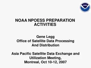
NPOESS Status. Vince Tabor Office of Satellite Data Processing and Distribution Asian Pacific Satellite Data Exchange and Utilization Meeting Seoul, June 1-3, 2005. Evolutionary Roadmap. 1960 - 2000. 2000 - 2010. 2010 – 2020+. DMSP (Defense Meteorological Satellite Program).

E N D
NPOESS Status Vince Tabor Office of Satellite Data Processing and Distribution Asian Pacific Satellite Data Exchange and Utilization Meeting Seoul, June 1-3, 2005
Evolutionary Roadmap 1960 - 2000 2000 - 2010 2010 – 2020+ DMSP(Defense Meteorological Satellite Program) NPOESS (National Polar Orbiting Operational Environmental Satellite System) NPP(NPOESS Preparatory Program) POES(Polar Orbiting Operational Environmental Satellites) EOS (Earth Observing System) Sensor data rate: 1.5 Mbps Data latency: 100-150 min. 15 Mbps sensor data rate Data latency: 100-180 min. Data availability: 98% Ground revisit time: 12 hrs. 20 Mbps sensor data rate Data latency: 28 min. Data availability: 99.98% Autonomy capability: 60 days Selective encryption/deniability Ground revisit time: 4-6 hrs.
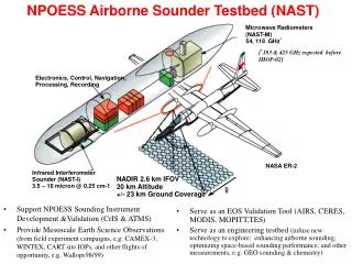
TSKY Field Terminals TOBS SafetyNetReceptors TATM LCL LATM LRN FOG eij MMC (Suitland) Schriever MMC System Overview 2. Downlink Raw Data 3. Transport Data to Centrals for Processing 1. Sense Phenomena Global fiber network connects 15 receptors to Centrals 4. Process Raw data into EDRs and Deliver to Centrals Monitor and Control Satellites and Ground Elements Full IDP Capability at each Central NESDIS, AFWA, FNMOC, NAVO 3
SSR Top Level Data Flow Description Sensor Packets VIIRS CMIS CrIS ATMS . . . ADCS +++ C3 3 2 1 . . . • (Encryption) • S/C C&DH assembles and labels Data Units C2 C1 • R-S Encoding • Viterbi enc. • Ka-band SMD 15 SafetyNet Receptors • Viterbi decode • R-S error correction • Buffer and forward valid Data Units to CONUS gateways via global fiber network Environmental Scene To Gateways • Satcom hop for McMurdo Data flow prototypes and characterizes end-to-end data format, protocol, and function to ensure efficient and reliable data delivery 4
1 2 5 6 7 3 7 8 9 7 7 6 3 3 2 1 5 6 9 8 Top Level Data Flow Description - II Data Handling Node (one at each Central) • Remove duplicates • Sort by time • (Decrypt) • Open Data Units to extract sensor packets Legend: C1 data units • Data Units from each satellite arrive at Centrals C2 data units Ingest subsystem Ingest C3 data units • Decompress • Chop into granules • Recover/assemble RDRs • Gateways multicast data to Centrals via CONUS fiber network SDR From Receptors EDR IDPS at each Central CONUS Gateways Delivery Data flow prototypes and characterizes end-to-end data format, protocol, and function to ensure efficient and reliable data delivery 5
Data Del Data Del Cal/Val Cal/Val Process Process Infra Infra Data Mgt Data Mgt Ingest Ingest State 1 – NPP Mission Only Risk Reduction Mission Phase TDRSS TDRSS GPS SpaceSegment NPP (1030) Svalbard Primary T&C NPP SMD C3Segment White Sands Complex LEO & A Backup T&C HRD Processing Demonstration FieldTerminal Segment LTA SDS AFWA NESDIS Launch SupportSegment Interface Data Processing Segment MMC at Suitland Flight Operations Team • Enterprise Management • Mission Management • Satellite Operations • Data Monitoring & Recovery One full set resides in each of the 2 Centrals Data Handling Node, Front End Processor NPP Stored Mission Data One full set resides in each of the 2 Centrals Command and Telemetry
Data Del Data Del Data Del Data Del Cal/Val Cal/Val Cal/Val Cal/Val Process Process Process Process Infra Infra Infra Infra Data Mgt Data Mgt Data Mgt Data Mgt Ingest Ingest Ingest Ingest NPOESS Stored Mission Data NPP Stored Mission Data Command and Telemetry State 2 – NPP & NPOESS Initial Operational Capability (IOC) TDRSS TDRSS GPS SpaceSegment ADCS NPOESSSpacecraft NPP (1030) 2130 1330 SARSAT Svalbard Primary T&C NPP SMD C3Segment White Sands Complex LEO & A Backup T&C HRD Field Terminal LRD FieldTerminal FieldTerminal Segment LTA SDS NAVO FNMOC AFWA NESDIS 15 Globally DistributedReceptor Sites Interconnectedby Commercial Fiber * * Patent Pending Launch SupportSegment Interface Data Processing Segment Schriever MMC Contingency Operations Team MMC at Suitland Flight Operations Team • Enterprise Management • Mission Management • Satellite Operations • Data Monitoring & Recovery One full set resides in each of the 4 Centrals Data Handling Node, Front End Processor One full set resides in each of the 4 Centrals
Data Del Data Del Data Del Data Del Cal/Val Cal/Val Cal/Val Cal/Val Process Process Process Process Infra Infra Infra Infra Data Mgt Data Mgt Data Mgt Data Mgt Ingest Ingest Ingest Ingest State 3 – NPOESS Full Operational Capability (FOC) TDRSS GPS SpaceSegment NPOESSSpacecraft 1330 1730 2130 Residuals ADCS SARSAT Svalbard Primary T&C NPP SMD C3Segment White Sands Complex LEO & A Backup T&C HRD Field Terminal LRD FieldTerminal FieldTerminal Segment LTA NAVO FNMOC AFWA NESDIS 15 Globally DistributedReceptor Sites Interconnectedby Commercial Fiber * * Patent Pending Launch SupportSegment Interface Data Processing Segment Schriever MMC Contingency Operations Team MMC at Suitland Flight Operations Team • Enterprise Management • Mission Management • Satellite Operations • Data Monitoring & Recovery One full set resides in each of the 4 Centrals NPOESS Stored Mission Data Data Handling Node, Front End Processor One full set resides in each of the 4 Centrals Command and Telemetry
NPOESS RF Link Summary(as filed with NTIA 10 April 2003) L5: 1176.45 MHz L2: 1227.6 MHz L1: 1575.42 MHz GPS TDRS Launch support and Backup T&C SESS beacons: 150.0 MHz 466.7 MHz 1066.7 MHz 3116.9 MHz 3200.3 MHz 3283.6 MHz SESS Topside Sounder 3 to 30 MHz T&C: S-band Command: 2067.3 MHz Telemetry: 2245 MHz • Svalbard, Norway • Primary T&C SARSAT: 406.05 MHz & 1544.5 MHz ADCS: 401.6 MHz & 466 MHz SMD: Ka-band 25.5 - 27 GHz HRD: X-band 7812 MHz Emergency Search & Rescue ALT: 5300 MHz & 13.575 GHz LRD: L-band 1704 MHz ARGOS / Advanced Data Collection System HRD Sites CMIS and ATMS Instruments use passive bands from 6 GHz to 183 GHz SafetyNet Sites LRD Sites NPP SMD: X-band: 8212.5 MHz
Ground Stations Portugal Forteleza Perth SafetyNet™ -- 15 globally distributed SMD receptors linked to the centrals via commercial fiber -- enables low data latency and high data availability
NPOESS EDR Processing Timeline Requirement: 95% of data delivered within 28 min. Capability: Delivering in 23.6 minutes Requirement: >77% of data delivered within 15 min. Capability: Delivering 80.3% Average < 10 min Earliest Data Delivered < 3 min
Average Data Latency Latency (minutes)
Real-Time Operational Demonstrations NPP (2008) CrIS/ATMS VIIRS OMPS Coriolis WindSat (2003) METOP (2005) IASI/AMSU/MHS & AVHRR NPOESS (2009) CrIS/ATMS, VIIRS, CMIS, OMPS & ERBS Aqua (2002) AIRS/AMSU/HSB & MODIS Use of Advanced Sounder Data for Improved Weather Forecasting/Numerical Weather Prediction NOAA Real-Time Data Delivery Timeline Ground Station Scenario NWS/NCEP GSFC/DAO ECMWF UKMO FNMOC Meteo-France BMRC-Australia Met Serv Canada NOAA Real-time User NWP Forecasts IDPS C3S Joint Center for Satellite Data Assimilation
Visible/Infrared Imager Radiometer Suite (VIIRS) Raytheon Santa BarbaraPrototype in assembly/qual, flight unit in production 0.4 km imaging and 0.8 km radiometer resolution 22 spectral bands covering 0.4 to 12.5 mm Automatic dual VNIR and triple DNB gains Spectrally and radiometrically calibrated EDR-dependent swath widths of 1700, 2000, and 3000 km Crosstrack InfraRed Sounder (CrIS) ITT Ft WaynePrototype in qualification, flight unit in production 158 SWIR (3.92 to 4.64 mm) channels 432 MWIR (5.71 to 8.26 mm) channels 711 LWIR (9.14 to 15.38 mm) channels 3x3 detector array with 15 km ground center-to-center 2200 km swath width Advanced Technology Microwave Sounder (ATMS)- NASA Northrop Grumman ElectronicsFlight unit in protoqual CrIS companion cross track scan Profiling at 23, 50 to 57, 183 GHz Surface measurements at 31.4, 88, 165 GHz 1.1, 3.3, and 5.2 deg (SDRs resampled) 2300 km swath width Ozone Mapping and Profiler Suite (OMPS) Ball AerospaceFlight unit in production Total ozone column 300 to 380 nm with 1.0 nm resolution Nadir ozone profile 250 to 310 nm with 1.0 nm resolution Limb ozone profile 290 to 1000 nm with 2.4 to 54 nm resolution Swath width of 2800 km for total column Development Sensor Highlights
Development Sensor Highlights (cont.) • Conical Scanning Microwave Imager/Sounder (CMIS)Boeing Space SystemsDelta PDR complete • 2.2 m antenna • RF imaging at 6, 10, 18, 36, 90, and 166 GHz • Profiling at 23, 50 to 60, 183 GHz • Polarimetry at 10, 18, 36 GHz • 1700 km swath width • Radio Interference (RFI) ECP complete, negotiations being wrapped up
Leverage Sensor Highlights • Radar Altimeter (ALT) • Alcatel • Measures range to ocean surface with a radar at 13.5 GHz • Corrects for ionosphere with 5.3 GHz radar • Corrects for atmosphere with CMIS water vapor measurements • Precise orbit determination with GPS • Earth’s Radiation Budget Suite (ERBS) • Northrop Grumman Space Technology • Three spectral channels • Total radiation measurement 0.3 to 50 mm • Shortwave Vis and IR measurement 0.3 to 5 mm • Longwave IR measurement 8 to 12 mm • Total Solar Irradiance Sensor (TSIS) • University of ColoradoAgreements in place, design underway • Two sensors for total irradiance (TIM) & spectral irradiance (SIM) • TIM measures total solar irradiance • SIM measures spectral irradiance 200 to 2000 nm • Pointing platform and sensor suite to be provided by CU LASP • Survivability Sensor (SS)
Highlights of Other Sensors • Space Environment Sensor Suite (SESS) • Ball AerospaceFinal instrument suite being selected, ECP in negotiations • Sensor suite collecting data on particles, fields, aurora, and ionosphere • Suite includes a UV disk imager (BATC), charged particle detectors (Amptek/U. of Chicago), thermal plasma sensors (UTD) • Will distribute suite on all 3 orbital planes • Advanced Data Collection System (ADCS) and Search and Rescue Satellite-Aided Tracking (SARSAT)ITAR agreements done, first integration TIMs underway • “GFE” to NPOESS from France and Canada • ADCS supports global environmental applications • SARSAT collects distress beacon signals • Aerosol Polarimetry Sensor (APS)Raytheon Santa Barbara Research CenterFull development on hold pending NASA satellite “Glory” plans • Aerosol characterizations of size, single scattering albedo, aerosol refractive index, aerosol phase function • Multispectral (broad, 0.4 to 2.25 mm) • Multiangular (175 angles) • Polarization (all states)
NPOESS P3I • Need for continued evolution recognized from the very beginning of NPOESS program • P3I requirements in paras 1.6 and 4.1.6.8 of IORD II • NASA’s role in NPOESS (per PDD) is technology development • P3I is built into the NPOESS program to : • Respond to changing/modified user needs • To track, monitor, and respond to identified user products that the current NPOESS system can not implement due to technological constraints. • Two forms of NPOESS P3I are envisioned • Modification of existing sensor to accomplish need • New sensor development required to implement need
Polar WV LoopsWinds improve Wx Fcst sfc mid-trop
NPOESS 1330 Configuration CMIS ATMS CrIS VIIRS ERBS OMPS Space Segment • Features • 150 Mbps Ka-band link with ample growth margin • Flexible, scalable avionics architecture • Solid State Recorder expandable to 1 terabits • Random Access for commanded re-transmission • Modular “plug and play” design with standard IEEE 1394 and 1553 • “Smart margins” throughout • High reliability spacecraft (0.9 / 7yrs) with graceful degradation • 45 days launch call-up from storage • Onboard fault management • Autonomous operations without commands up to 60 days • Robust propulsion system • On-board data compression • Optimal redundancy Single satellite design for all orbits with common sensor accommodation
NPOESS / NPP Sensor Manifest 1330 1730 2130 1030NPP VIIRS VIIRS VIIRS VIIRS CMIS CMIS CMIS CrIS CrIS CrIS ATMS ATMS ATMS SESS GPSOS SS SS SS SARSAT SARSAT SARSAT ADCS ADCS ERBS OMPS OMPS ALT APS TSIS
Atm Vert Moist Profile Precipitable Water Cloud Top Pressure Atm Vert Temp Profile Cloud Top Temperature Precipitation Type/Rate Imagery Down LW Radiance (Sfc) Pressure (Surface/Profile) Sea Surface Temperature Down SW Radiance (Sfc) Sea Ice Characterization Sea Surface Winds Electric Fields Sea SFC Height/TOPO Soil Moisture Electron Density Profile Snow Cover/Depth Energetic Ions Aerosol Optical Thickness Solar Irradiance Aerosol Particle Size Geomagnetic Field Supra-Therm-Aurora Prop Ice Surface Temperature Aerosol Refractive Index Surface Type Albedo (Surface) In-situ Plasma Fluctuation Surface Wind Stress Auroral Boundary In-situ Plasma Temp Suspended Matter Ionospheric Scintillation Auroral Energy Deposition Total Water Content Med Energy Chgd Parts Auroral Imagery Vegetative Index Land Surface Temp Cloud Base Height LEGEND Net Heat Flux Cloud Cover/Layers VIIRS GPSOS Net Solar Radiation (TOA) Cloud Effective Part Size CMIS ERBS Neutral Density Profile Cloud Ice Water Path TSIS CrIS/ATMS Cloud Liquid Water Ocean Color/Chlorophyll ALT OMPS SES APS Cloud Optical Thickness Ocean Wave Character - KPPs Cloud Particle Size/Distrib Outgoing LW Rad (TOA) Cloud Top Height O3 – Total Column Profile Sensor Suite vs EDR Requirements
Low-Risk Launch Vehicle Integration • EELV SIS compatible • EELV-M 4-meter fairing accommodates satellite • Satellite design compliant with Delta IV and Atlas V • Baseline is Delta IV out of VAFB • Sun-synch 828 km orbit • No launch vehicle design integration issues • Standard electrical, mechanical interfaces • Interface control, with launch service contractor • Launch processing planned – NPOESS will be third EELV launch for NGST team • Transportation • Facilities • Processing • Launch Delta IV (4,0) Atlas V400 EPF Standard interfaces ease integration with both launch vehicles
Mission Management Center • Includes mission planning, satellite and ground asset monitor and control, and enterprise management • Enterprise-wide, hierarchical views into operational ‘real-time’ performance give the operators the necessary information to keep mission data delivered in a timely and highly available manner • Hierarchical and user friendly software displays combined with a well-balanced mix of automated software and operator controlled procedures allow for a small cost-effective operations staff to be deployed yet maintain full oversight and control of mission operations • Primary MMC, located in Suitland, Maryland, initially for NPP with operations expanded for NPOESS • Schriever MMC, located at Schriever AFB, Colorado, prior to launch of the first NPOESS satellite MMC element provides tools and staff to effectively manage the overall NPP/NPOESS mission
Field Terminal Segment Design • Dual use of IDPS software provides a best-value design that combines software and hardware flexibility, expandability, and robustness to meet stringent performance requirements • IDPS designed with sufficient forethought to ensure it meets FTS needs • JTA and DII COE Level 6 compliance minimize impacts to user interfaces and field terminals • Lower development and maintenance costs • FT users get timely access to latest algorithms ensuring quality EDRs • Provides interoperability and hardware platform options • Flexible design ensures users get the data they need when they need it • Programmable downlink that favors high-resolution imagery and provides flexibility for the future • Flexible ancillary data approach (critical ancillary data via satellite downlink for LRD) • Data compression, channel selection
Program Summary • Program is making significant technical progress • Overcoming problems as they develop • Ongoing effort with contractors to ensure budget control • Sensor overruns are straining the budget • VIIRS is beginning to show some light down toward the end of the tunnel • Cryocooler test currently underway shows that the basic design/performance issue is the result of mechanical failures NOT the basic radiator design • We have adjusted the CrIS and OMPS schedules to hold down FY05 expenditures without creating another critical path • NGST and IPO are working with Ball and NASA to plan an efficient integration process • Once we settle on a VIIRS final schedule, we will establish new launch dates
Watch List – 15 March 2005 • VIIRS: • EDU Cryoradiator failure to cool FPA sufficiently – Root cause analysis is in progress to determine if this is a design problem (common to FU1), an EDU workmanship issue, or due to test instrumentation problems (or some combination of these). Bare cryoradiator in T/V results look good. Baseline mitigation approach is to adopt ULTEM rigid mount isolators (struts or bipods) between stages instead of launch locks, but also carrying 2 launch lock alternatives (active, passive). • Earthshine contamination on the Solar Diffuser – Recommended solutions selected by NGST-led working group from brainstorming inputs and consideration of effectiveness and manufacturability. Most affected EDR is OC/C. • DNB offset knowledge – Analysis focus on how much residual error can be tolerated and still meet EDR performance, to be verified with users at AFWA (in case we confront eventual “use as is” decision). Meanwhile, FPGA code change for DNB readout timing (synchronous w/ TDI clocks) expected to eliminate/reduce the variable offsets at their source is nearing test. • OMPS: • TC defocus – Slit length determined not to be root cause - analysis concentrating on optics and identification of root cause and impact on EDR performance. • CrIS: • FPA performance degradation over time – Analysis focus on identification of acceptance criteria for flight FPAs and characterization and mitigation of LWIR detector degradation. • CMIS: • Warm load temperature uncertainty – Meeting with JPL and Aerospace experts conducted; focus on warm load cover and associated temperature uniformity, knowledge, and calibration performance. • Spectral response characterization – Focus on EDR performance impact based on analysis of brightness temperature sensitivity to passband settability and stability by AER. • ATMS: • Gunn Diode reliability – channels 16-22 have decreased reliability. Focus on EDR performance impact if those channels are not operational: initial results show that the microwave-produced moisture profiles are highly degraded, as expected.