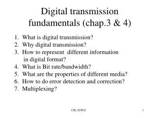
Download
1 / 38
380 likes | 586 Views
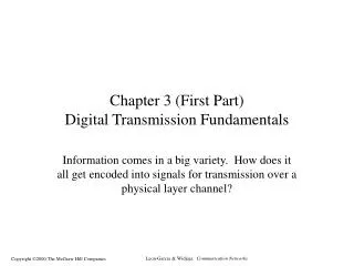
Stephen Kim dskim@iupui.edu. Session 3. Digital Transmission Fundamentals. Transmission Systems. Network – The Transmission Infrastructure What to be transmitted? (object) What to transmit through? (medium). Communication Channel. transmitter. Receiver. Data Communication.

E N D
Stephen Kim dskim@iupui.edu Session 3.Digital Transmission Fundamentals
Transmission Systems • Network – The Transmission Infrastructure • What to be transmitted? (object) • What to transmit through? (medium)
Communication Channel transmitter Receiver Data Communication • Propagation of energy in the form of pulses. • Analog Communication • Transmit a waveform – varying continuously on time • Reproduce the waveform as exactly as possible at a remote site. • Digital Communication • Transmit a symbol from a finite set • Thru transmission medium or channel • Binary – {1, 0} • 1 – send a positive voltage for a certain period of time (t) • 0 – send a negative voltage for t • Receiver determine the input symbol with high probability
Advantage of Digital Comm. • Can a digital signal go longer than an analog signal? • Can we make a digital signal to go longer than an analog signal? • Distortion of electrical signal along the distance • Attenuation • Noise • from other electrical systems • from other electrical cables • from nowhere (random noise) • Solutions • make the medium insensitive to noise • shielded wire • eliminate the noise source – how? • repeater – regenerate the signal
S Repeater Repeater D Attenuated and distorted signal +noise Recovered signal +residual noise Amp Equalizer Repeater • Periodically regenerate the signal • Amplifier for attenuated signal • Equalizer to eliminate the distortion • Accumulation of noise
S Repeater Repeater D Attenuated and distorted signal +noise Receptor Bit Generator Transmitter Recovered signal Repeater in Digital Transmission • The symbol is recovered every time by the repeaters. • No accumulation of noise • Quality of signal is independent of distance
A(f) 1 0 Bandwidth • Range of frequencies passed by a channel • Attenuation is a function of frequency as well as distance • Amplitude-response function A(f) = Amplitude of output tone / Amplitude of input tone f
3 3 2 2 2 2 1 1 0 0 0 0 0 0 Nyquist’s Theorem • If a signal run thru a low-pass filter of bandwidth W, the filtered signal can be reconstructed by making only 2W samples per second. • The fastest pulse rate = 2W pulse/second. • Example • A noiseless 3-kHz channel can transmit binary signals at most at a rate of 6000 bit/sec. • Multilevel Transmission • Each pulse represents M levels, then the pulse can encode log2M binary. • A noiseless W-Hz channel can transmit at a bit rate of 2W·log2M.
Low SNR t t t Signal-to-Noise Ratio (SNR) • Without noise, we can send information at any bit rate. • Large M • SNR = Signal power / Noise power • dB = 10 log10(S/N) High SNR t t t signal noise signal + noise
Shannon Channel Capacity • Maximum bit rate, C=W·log2(1+S/N) • Example • Bandwidth 3400Hz, • SNR = 40dB • C= 3400 log2(1+10000)=45Kbps • No matter how often sample are taken or how many levels are encoded.
Aoutcos (2ft + (f)) Aincos 2ft Channel t t Frequency Domain • Attenuation – Aout/Ain • Phase shift - (f) • Cascade of filters, or channels from various sources Output Signal of the Channel y(t)
Fourier Analysis – 1 A periodic function g(t) is described by
Fourier Analysis – 2 • Consider any 8-bit word, say 01100010 • T=8, f=1/8, • g(1)=0, g(2)=1, g(3)=1, g(4)=0, g(5)=0, g(6)=0, g(7)=1, g(8)=0
1 1 1 0 0 0 0 0 T Fourier Analysis – 3 N=1 N=2 N=4 N=8
1 0 1 0 1 1 1 0 0 Line Coding – 1 • How to convert a binary sequence into a digital signal • Cosinderation • Maximizing the bit rate • Easy to implementation • Cost of network systems • Embedding synchronization • Built-in error detection • Immunity to noise and interference • Unipolar NRZ encoding • simple • A binary 1 for +A voltage • A binary 0 for 0 voltage • Disadvantage – power for transmission
1 0 1 0 1 1 1 0 0 Line Coding – 2 • Polar NRZ Encoding • A binary 1 for +A/2 voltage • A binary 0 for –A/2 voltage • Efficient transmission power • Problem in NRZ Encodings • If there is a long sequence of 0’s, or a long sequence of 1’sthe encodings generate a low frequency • Some network components consider a low frequency as a noise, so eliminate it. • Example, telephone system filters out frequencies lower than 200Hz.
1 0 1 0 1 1 1 0 0 Line Encoding – 3 • Bipolar Encoding • A binary 0 is mapped to 0 voltage. • A consecutive 1s are alternatively mapped to +A/2 and –A/2. • No low frequency signal • Synchronization • Determine the boundary between bits. • Using NRZ encodings or Bipolar encoding, need of separate synchronization signal
1 0 1 0 1 1 1 0 0 Manchester encoding Differential Manchester encoding Line Encoding – 4 • Manchester Encoding • A binary 1 is denoted by a transition from +A/2 to –A/2 in the middle of the bit time interval. • A binary 0 is denoted by a transition from –A/2 to +A/2. • Every bit contributes a transition that is used for synchronization. • Doubled pulse rate • Applied to Ethernet LAN • Differential Manchester Encoding • A transition in the middle of every bit time • Transition in the beginning of the bit interval represents a binary 0. • No transition in the beginning of the bit interval represents a binary 1. • Applied to Token-ring
Line Encoding – 5 • The Manchester code is an 1B2B code scheme. • 1 bit information is encoded 2-bit signal. • 0 is mapped to 01, 1 is mapped to 10. • FDDI (Fiber Distributed Data Interface) • use 4B5B • 4 bit information is encoded 5-bit signal
Property of Communication MediaThe Big Picture • Propagation speed c/f • c – speed of light (3x10⁸m/sec), f – frequency • Guided Media – Wired media • Point-to-point, so discrete network topologies • Unlimited resource • simply install more wires, expensive though. • Attenuation 10^<distance>, exponential • Twisted pair, Coaxial cable, Fiber optic • Unguided Media – wireless media • Broadcast with limited directionality • Broad and continuous network topologies • Limited resource, so regulated by some organizations • Inexpensive to be installed • Attenuation <distance>^2, quadratical • Radio, Infrared light
Reflected path Direct path Wired Media • Twisted Pair • Two parallel insulated wires • one for signal, another for reference (ground) • Crosstalk • Many cables are usually bundled • A cable talks to other adjacent cable. • Twist the pair of wires • Let them (signal&reference) catch same noise • Coaxial cable • Better immunity to noise and interference • Optical fiber • On-Off pulse on the guided medium • No interference with electromagnetic • Multimode mode and Single mode
Wireless Media • Radio • Frequency • Low frequency – can pass obstacles, but quick power dissipation • High frequency – can travel in straight; bounce off obstacles; absorbed by rain; Multipath fading • Multipath fading – bounced signal are cancelled direct signal. • Regulated by government agency • Infrared Light • Cannot penetrate walls • Directional • No regulation
Overview of Error Detection and Correction • Highly reliable modern communication • Non-zero error probability • Error-sensitive digital communication • Compressed information, no redundancy, distinct roles of data • How to handle errors • ARQ • Automatic Retransmission reQuest • detect and send a request for retransmission • bandwidth redundancy • FEC • Forward Error Correction • detect and correct • embedded redundancy
Error Detection – Single Parity Check • Codeword = information bits & check bit • Two Choices • Even parity - # of 1s in the codeword is 2n. • Odd parity - # of 1s in the codeword is 2n+1. • mostly use the even parity method. • Modulo k arithmetic - concern with remainder alone. • k 2k 3k …, k+1 2k+1 3k+1 … • ex) (modulo 3) 3693n, 47103n+1, 58113n+2 • The parity is (modulo 2) operation for individual bits in the codeword. • ex) 1001010 (1+0+0+1+0+1+0) modulo 2 = 1 • A sender attaches the result as an additional bit. • A recipient computes the even # of 1s in every codeword. • Ability of the single parity check
Internet CheckSum • A Checksum is calculated for the header • The header is modified by an Internet router, sothe checksum must be re-calculated at every router • Seek for an efficient software • Assume a header contain L words(b0 to bL-1), and then add a word (checksum word, bL). • x = b0 + b1 + … + bL-1 modulo 2L – 1 • bL = -x
data data/alarm data+redn (data . redn)error S R + error Principle of Error Detection • Hamming Distance • Hypercube • Valid codeword or Invalid codeword
A Hypercube 1110 0110 0111 1111 1100 0100 0101 1101 1011 0011 1001 0010 0001 1010 0000 1000
d Distance between 2 Valid Codeword • The minimum distance is d , so as to detect d-1 errors • Can we make codeword to detect 3 bit errors? • 00000011, 00001100, 00110000, 11000000 • Eg) 8-bit word => 256 possible codes • Select codewords as many as possible so that the minimum distance is 4.
Principle of Error Correction • If recipient receives an invalid code, make it go to the nearest valid code. • To correct t errors, the distance is at least 2t+1. • Correction of single bit errors • m message bits, r check bits • Each valid codeword is surrounded by m+r invalid codeword. • So, there are at least (m+r+1)2mcodeword • In addition, m+r bits can make 2 (m+r) combinations • (m+r+1) 2 r • m=7, then 8+r 2 r, the smallest r is 4.
Error Models • To measure the effectiveness of error detection/correction,need to know the behavioral property of the errors. • Error is considered as a binary vector of length n (size of codeword) • Model • Random error vector model • All 2m possible error vectors are equally likely to occur. • P(0000)=P(0001)=P(1111) • Random bit error model • The bit errors occur independently of each other. • p = a single bit error, P(j errors) = nCj pj (1-p)n-jP(no error) = (1-p)n, P(any error) = 1–(1-p)n np • Burst error model • low error period + high error period • random bit error model & random error vector model • Close to most communication channel
Error Detection Failure for Single Parity • In Random error vector model • In Random bit error model • In Burst error model • Hard to say
Cyclic Redundancy Check (CRC) • S and R agree upon a generator function g(x) of degree n. • Use binary and modulo-2 arithmetic • no carry for addition, no borrow for subtraction • addition = subtraction = exclusive OR. • n is the degree of g(x). f(x) Is xnf(x)-r(x)+e(x) divisible by g(x) ? S g(x) R g(x) xnf(x)-r(x) xnf(x)-r(x)+e(x) + g(x)*s(x) g(x)*s(x)+e(x) xnf(x)=g(x)*s(x)+r(x) e(x)
111 1011 1100000 1011 111000 1011 10100 1011 10 Example of CRC • g(x) = x3+x+1 = 1011 • f(x) = x3+x2 = 1100 • xnf(x) = x6+x5 = 1100000 xnf(x)+r(x)=x6+x5+x=1100010 Transmit No error 1100010 is divisible by 1011
Capability of CRC • Detect all single errors if g(x) cannot divide xi. • Detect all double errors if g(x) cannot divide 1+xm , where m is the bit distance b/w two error bits. • For a primitive polynomial of degree N, the smallest m is 2N-1, for which 1+xm is divisible by the primitive. • ex) g(x) has a factor of a primitive polynomial of degree 15, it will not divide 1+xm for any m below 32768. x15+x+1 is such a polynomial. • Detect all triple error if g(x) contains x+1 as a factor. • Detect all burst error of length n, where n is the degree of the generator function. • e(x) is not divisible by g(x) if deg[e(x)] < deg[g(x)] • All generator function is (x+1)p(x). • (CRC-8) x8+x2+x+1 • (CRC-16) x16+x15+x2+1
Advanced Topic: Graph Coloring • The error detection (or correction) problem can be mapped to a graph coloring problem. • General Graph Coloring • For an undirected graph G=(V,E) • Assign a color to each vertex such that the color is different from its neighbors with the minimum number of color used. • The color index will be the redundancy. • It is known to unsolvable. • For a planar graph, the number of colors seems to be 4. • Nobody proved it yet, many believed so. • For a hypercube, the number of colors is 2 (0 or 1). • n-D hypercube (a binary number of length n) a=[an an-1…a1] • The color is a*[1111…1]T
Expanded Graph Coloring • Xk = the minimum number of colors in a vertex-coloring such that any two vertices with distance exactly k. • Yk = the minimum number of colors in a vertex-coloring such that any two vertices within distance k. • For a binary a of length n, consider nlog(n) m If the distance of a and b is 2, then am bm Proof? (do it yourself if you are interesting at)
Expanded Graph Coloring • The matrix T will assign different colors within distance 3. • So, we solved Xk and Yk for k3. • Why? • How about Xk and Yk for k>3 ? • There is a solution, but it is complicated.