Download
1 / 39
390 likes | 597 Views
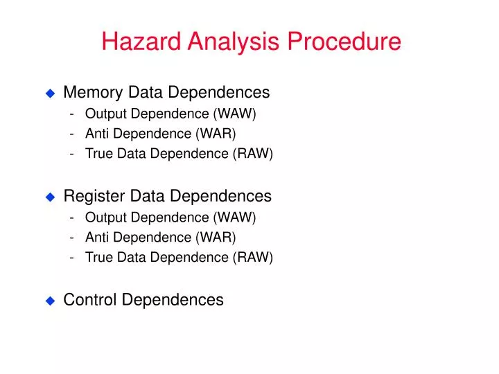
Hazard Analysis Procedure. Memory Data Dependences Output Dependence (WAW) Anti Dependence (WAR) True Data Dependence (RAW) Register Data Dependences Output Dependence (WAW) Anti Dependence (WAR) True Data Dependence (RAW) Control Dependences. Terminology. Pipeline Hazards:

E N D
Hazard Analysis Procedure • Memory Data Dependences • Output Dependence (WAW) • Anti Dependence (WAR) • True Data Dependence (RAW) • Register Data Dependences • Output Dependence (WAW) • Anti Dependence (WAR) • True Data Dependence (RAW) • Control Dependences
Terminology • Pipeline Hazards: • Potential violations of program dependences • Must ensure program dependences are not violated • Hazard Resolution: • Static Method: Performed at compiled time in software • Dynamic Method: Performed at run time using hardware Stall, Flush or Forward • Pipeline Interlock: • Hardware mechanisms for dynamic hazard resolution • Must detect and enforce dependences at run time
Necessary Conditions for Data Hazards stage X j:rk_ Reg Write j:rk_ Reg Write j:_rk Reg Read iOj iAj iDj stage Y Reg Write Reg Read Reg Write i:rk_ i:_rk i:rk_ WAW Hazard WAR Hazard RAW Hazard dist(i,j) dist(X,Y) ?? dist(i,j) > dist(X,Y) ?? dist(i,j) dist(X,Y) Hazard!! dist(i,j) > dist(X,Y) Safe
Pipelining: Steady State t0 t1 t2 t3 t4 t5 Insth IF ID RD ALU MEM WB Insti IF ID RD ALU MEM WB Instj IF ID RD ALU MEM WB Instk IF ID RD ALU MEM Instl IF ID RD ALU IF ID RD IF ID F
Pipelining: Data Hazards t0 t1 t2 t3 t4 t5 Insth IF ID RD ALU MEM WB i Insti IF ID RD ALU MEM WB j Instj IF ID RD ALU MEM WB Instk IF ID RD ALU MEM Instl IF ID RD ALU IF ID RD i: rk _ j: _ rk IF ID F
t0 t0 t0 t1 t1 t1 t2 t2 t2 t3 t3 t3 t4 t4 t4 t5 t5 t5 Insth Insth Insth IF IF IF ID ID ID RD RD RD ALU ALU ALU MEM MEM MEM WB WB WB i i i Insti Insti Insti IF IF IF ID ID ID RD RD RD ALU ALU ALU MEM MEM MEM WB WB WB j j j Instj Instj Instj IF IF IF ID ID ID Stalled in RD Stall Stall RD ALU RD ALU RD MEM Instk Instk Instk IF IF IF Stalled in ID Stall Stall ID RD ID RD ALU ID Instl Instl Instl Stall Stalled in IF Stall IF ID IF RD IF ID IF IF ID i: rk _ bubble j: _ rk i: rk _ bubble bubble bubble j: _ rk i: rk _ bubble bubble j: _ rk F Pipelining: Stall on Data Hazard Stall==make the younger instruction wait until the hazard has passed 1. stop all up-stream stages 2. drain all down-stream stages
t1 t2 t3 t4 t5 t6 t7 t8 t9 t10 Ij Ik Il stall Il stall Il stall Il Ii Ij Ik stall Ik stall Ik stall Ik Il Ih Ii Ij stall Ij stall Ij stall Ij Ik Il Ih Ii nop nop nop Ij Ik Il Ih Ii nop nop nop Ij Ik Il Ih Ii nop nop nop Ij Ik Pipeline: Stall on Data Hazard t0 IF Ii ID Ih RD ALU MEM WB
case 3: • i: rk _ • j: rk _ • k: rk _ • l: _ rk • case 4: • i: rk _ • j: _ rk • k: _ rk • l: _ rk What should these cases look like? t0 t1 t2 t3 t4 t5 Insth IF ID RD ALU MEM WB i Insti IF ID RD ALU MEM WB j Instj IF ID RD ALU MEM WB Instk IF ID RD ALU MEM Instl IF ID RD ALU IF ID RD • case 1: • i: rk _ • j: .... • k: _ rk • case 2: • i: rk _ • j: .... • k: .... • l: _ rk IF ID F
Stall Conditions How many scenarios could trigger a particular hazard?
Inter-instruction Control Hazards Can we use pipeline stall to resolve control hazards?
Pipeline: Control Hazard t0 t1 t2 t3 t4 t5 i IF ID RD ALU MEM WB i+1 IF ID RD ALU MEM WB i+2 IF ID RD ALU MEM WB i+3 IF ID RD ALU MEM i+4 IF ID RD ALU i: br k i+1: xxxxxx k: yyyyyy IF ID RD IF ID F
Pipeline: Control Hazard t0 t1 t2 t3 t4 t5 IFi IDi RDi ALUi MEMi WBi IFi+1 IDi+1 RDi+1 ALUi+1 Squashed Instructions IFi+2 IDi+2 RDi+2 IFi+3 IDi+3 IFi+4 i: br k i+1: xxxxxx k: yyyyyy IFk IDk RDk IFk+1 IDk+1 IFk+2
t0 t1 t2 t3 t4 t5 t6 t7 t8 t9 t10 IF Ii Ii+1 Ii+2 Ii+3 Ii+4 Ik Ik+1 Ik+2 Ik+3 Ik+4 Ik+5 ID Ii Ii+1 Ii+2 Ii+3 nop Ik Ik+1 Ik+2 Ik+3 Ik+4 RD Ii Ii+1 Ii+2 nop nop Ik Ik+1 Ik+2 Ik+3 ALU Ii Ii+1 nop nop nop Ik Ik+1 Ik+2 MEM Ii nop nop nop nop Ik Ik+1 WB Ii nop nop nop nop Ik Pipeline Flush on Control Hazards
IDk+1 IFk+2 Delayed Branches t0 t1 t2 t3 t4 t5 i: IFi IDi RDi ALUi MEMi WBi i+1: IFi+1 IDi+1 RDi+1 ALUi+1 MEMi+1 WBi+1 Branch Delay Slots i+2: IFi+2 IDi+2 RDi+2 ALUi+2 MEMi+2 WBi+2 i+3: IFi+3 IDi+3 RDi+3 ALUi+3 MEMk+3 i+4: IFi+4 IDi+4 RDi+4 ALUi+4 k: IFk IDk IFk+2 k+1: IFk+1 k: yyyy . . . . i: Br. to k: i+1: xxxx . . . . k+2:
Forwarding Path Analysis t0 t1 t2 t3 t4 t5 Insti IF ID RD ALU MEM WB Insti+1 IF ID RD ALU MEM WB Insti+2 IF ID RD ALU MEM WB Insti+3 IF ID RD ALU MEM Insti+4 IF ID RD ALU IF ID RD IF ID F
IF ID RD b a c ALU ALU MEM FORWARDING PATHS WB Implementation of Pipeline Interlock: ALU dist=1 dist=2 dist=3 i+1: _ RX i+2: _ RX i+3: _ RX i+2: Rz _ i: RX _ i+1: Ry _ i+1: RY _ i: RX _ i: RX _ (i i+1) Forwarding via Path a (i i+2) Forwarding via Path b (i i+3) i writes R1 before i+3 reads R1
IF ID RD e d ALU LOAD FORWARDING PATH(s) MEM WB Forwarding Path(s) for Load Instructions: dist=1 dist=2 dist=3 i+1: _ RX i+2: _ RX i+3: _ RX i+2: Rz _ i: RX mem[ ] i+1: Ry _ i+1: RY _ i: RX mem[ ] i: RX mem[ ] (i i+1) Stall i+1 (i i+1) Forwarding via Path d (i i+2) i writes R1 before i+2 reads R1
• • Register File • • • • • Comp Comp Comp Comp 1 0 1 0 1 0 1 0 • 1 0 1 0 ALU ALU • • Load Forwarding Path • A d d r D-Cache D a • t a • LOADWB • • LOADMEM Stall IF,ID,RD,ALU
Load Delay Slot (MIPS R2000) t0 t1 t2 t3 t4 t5 i: IF ID RD ALU MEM WB j: IF ID RD ALU MEM WB k: IF ID RD ALU MEM WB - The effect of a “delayed” Load is not visible to the instructions in its delay slots. h: Rk -- …… i: Rk MEM[ - ] j: -- Rk k: -- Rk Which (Rk) do we really mean?
Interrupts • An unexpected transfer of control flow • Control is given to a system program and later given back (restartable) • Transparent to the interrupted program • Asynchronous Interrupt (e.g. I/O) can be taken at some convenient point • Synchronous Interrupt (e.g. divide by 0) is associated with a particular instruction interrupt H1 i1 H2 i2 restart …. i3 Hn
Sequential Code Semantics Overlapped Execution i1: i1: xxxx i1 i2: i2: xxxx i2 i3: i3: xxxx i3 Precise Interrupts A precise interrupt appears (to the interrupt handler) to take place exactly between two instructions
What to Do on an Interrupt • Find the point of interrupt in the instruction stream • Allow instructions prior to the interrupt point to complete • Save enough state to allow restarting at the same point • Program Counter, status registers, etc. (registers that are clobbered during transition) • Why not general purpose register file?? • Start executing from a pre-specified interrupt handler address • Almost always involves a change in “protection mode” • Must be careful to not leave any loophole such that a draining user instruction can act like a “privileged” instruction during transition • “Return-from-Interrupt” Instruction: Jump to the saved PC and also restore clobbered states from saved copies
IBM’s Experience on Pipelined Processors [Agerwala and Cocke 1987] Attributes and Assumptions: • Memory Bandwidth • at least one word/cycle to fetch 1 instruction/cycle from I-cache • 40% of instructions are load/store, require access to D-cache • Code Characteristics (dynamic) • loads - 25% • stores - 15% • ALU/RR - 40% • branches - 20% 1/3 unconditional (always taken); • 1/3 conditional taken; • 1/3 conditional not taken
More Statistics and Assumptions • Cache Performance • hit ratio of 100% is assumed in the experiments • cache latency: I-cache = i; D-cache = d; default: i=d=1 cycle • Load and Branch Scheduling • loads: • 25% cannot be scheduled • 75% can be moved back 1 instruction • branches: • unconditional - 100% schedulable • conditional - 50% schedulable
CPI Calculations I • No cache bypass of reg. file, no scheduling of loads or branches • Load Penalty: 2 cycles (0.25*2=0.5) • Branch Penalty: 2 cycles (0.2*0.66*2=0.27) • Total CPI: 1 + 0.5 + 0.27 = 1.77 CPI • Bypass, no scheduling of loads or branches • Load Penalty: 1 cycle (0.25*1=0.25) • Total CPI: 1 + 0.25 + 0.27 = 1.52 CPI
CPI Calculations II • Bypass, scheduling of loads and branches • Load Penalty: 75% can be moved back 1 => no penalty remaining 25% => 1 cycle penalty (0.25*0.25*1=0.063) • Branch Penalty: 1/3 Uncond. 100% schedulable => 1 cycle (.2*.33=.066) 1/3 Cond. Not Taken, if biased for NT => no penalty 1/3 Cond. Taken 50% schedulable => 1 cycle (0.2*.33*.5=.033) 50% unschedulable => 2 cycles (.2*.33*.5*2=.066) • Total CPI: 1 + 0.063 + 0.167 = 1.23 CPI
CPI Calculations III • Parallel target address generation • 90% of branches can be coded as PC relative i.e. target address can be computed without register access • A separate adder can compute (PC+offset) in the decode stage • Branch Penalty: • Conditional: Unconditional: • Total CPI: 1 + 0.063 + 0.087 = 1.15 CPI = 0.87 IPC
k-stage pipelined unpipelined T/k T S T/k S Pipelined Depth (T/ k +S ) ?
Limitations of Scalar Pipelines • Upper Bound on Scalar Pipeline Throughtput Limited by IPC = 1 • Inefficient Unification Into Single Pipeline Long latency for each instruction • Performance Lost Due to Rigid Pipeline Unnecessary stalls
Stalls in an Inorder Scalar Pipeline Instructions are in order with respect to any one stage i.e. no dynamic reordering