Download
1 / 33
440 likes | 1.35k Views
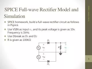
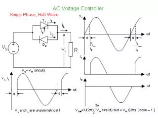
Single-Phase Half-Wave Rectifier. Waveforms. Single-Phase Half-Wave Rectifier. Performance Parameters. Average value of the output voltage, V dc Average value of the output current, I dc Output dc power, P dc P dc = V dc I dc rms value of the output voltage, V rms Output ac power, P ac

E N D
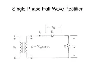
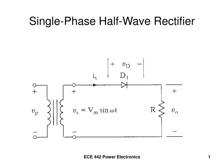
Single-Phase Half-Wave Rectifier ECE 442 Power Electronics
Waveforms ECE 442 Power Electronics
Single-Phase Half-Wave Rectifier ECE 442 Power Electronics
Performance Parameters • Average value of the output voltage, Vdc • Average value of the output current, Idc • Output dc power, Pdc • Pdc = VdcIdc • rms value of the output voltage, Vrms • Output ac power, Pac • Pac = VrmsIrms ECE 442 Power Electronics
Performance Parameters (continued) • Efficiency, η • η = Pdc/Pac • Effective (rms) value of the ac component of the output voltage, Vac • Vac = Vrms2 – Vdc2 • Form factor, FF • FF = Vrms/Vdc • Ripple factor, RF • RF = Vac/Vdc ECE 442 Power Electronics
Performance Parameters (continued) • Alternate form for ripple factor • Transformer utilization factor, TUF • TUF = Pdc/VsIs • Vs, Is are rms voltage and current of the transformer secondary ECE 442 Power Electronics
Input Voltage and Current ECE 442 Power Electronics
Performance Parameters (continued) • Displacement angle, Φ • Displacement Factor, DF • DF = cos(Φ) • Harmonic Factor, HF ECE 442 Power Electronics
Performance Parameters (continued) • Power Factor, PF ECE 442 Power Electronics
Performance Parameters (continued) • Crest Factor, CF ECE 442 Power Electronics
Example 3.1 • Determine η, FF, RF, TUF, PIV of the diode, CF of the input current, input PF. ECE 442 Power Electronics
Determine the Average Voltage, Vdc ECE 442 Power Electronics
Determine the rms Voltage, Vrms ECE 442 Power Electronics
Determine Pdc, Pac, and η ECE 442 Power Electronics
Determine FF and RF ECE 442 Power Electronics
Determine the TUF ECE 442 Power Electronics
Determine the PIV • PIV is the maximum (peak) voltage that appears across the diode when reverse biased. Here, PIV = Vm. - PIV - + + ECE 442 Power Electronics
Determine CF ECE 442 Power Electronics
Determine PF ECE 442 Power Electronics
Summary – Half-Wave Rectifier • RF=121% High • Efficiency = 40.5 Low • TUF = 0.286 Low • 1/TUF = 3.496 • transformer must be 3.496 times larger than when using a pure ac voltage source ECE 442 Power Electronics
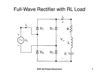
Half-Wave Rectifier with R-L Load ECE 442 Power Electronics
Waveforms of Current and Voltage Conduction period of D1 extends beyond ωt = π ECE 442 Power Electronics
Average Output Voltage Increase average voltage and current by making σ = 0 ECE 442 Power Electronics
Waveforms with Dm installed ECE 442 Power Electronics
Application as a Battery Charger Diode conducts for vs > E, starting when Vmsinα = E ECE 442 Power Electronics
Waveforms for the Battery Charger Diode turns off when vs < E (at β = π – α) Charging current io = (vs – E)/R io = (Vmsinωt – E)/R for α < ωt < β ECE 442 Power Electronics
Single-Phase Full-Wave Rectifier Center-Tapped Transformer ECE 442 Power Electronics
Waveforms for the Full-Wave Rectifier ECE 442 Power Electronics
Single-Phase Full-Wave Rectifier PIV = 2Vm ECE 442 Power Electronics
Full-Wave Bridge Rectifier ECE 442 Power Electronics
Waveforms for the Full-Wave Bridge ECE 442 Power Electronics
Full-Wave Bridge with Waveforms Conduction pattern D1 – D2 D3 – D4 PIV = Vm ECE 442 Power Electronics