Download

1 / 29
290 likes | 313 Views
The Front End Test Stand (FETS) project demonstrates next-gen accelerator technologies with high beam quality and efficient control to reduce beam loss. The FETS team collaborates with universities to mentor the next generation of accelerator experts. Key components include high-brightness H- ion source, beam chopper, RFQ, and comprehensive diagnostics.

E N D
The RAL Front End Test Stand Alan Letchford CCLRC RAL ISIS Injector Group Joint Accelerator Workshop 28–29 March 2006
The Front End Test Stand (FETS) is a collaborative project, between CCLRC and UK universities, to design and construct a test stand for demonstrating key technologies for the front end of next generation high power accelerators. By working closely with young university teams it is hoped to pass on the wealth of knowledge and experience of CCLRC staff to the next generation of accelerator engineers/physicists. The FETS team has members from ASTeC and ISIS as well as the physics departments of Imperial College London and Warwick University.
The FETS team John Back (Warwick) Aaron Cheng (Imperial) Mike Clarke-Gayther (ISIS) Dan Faircloth (ISIS) Simon Jolly (Imperial) Ajit Kurup (Imperial) David Lee (Imperial) Alan Letchford (ISIS) Ciprian Plostinar (ASTeC) Jürgen Pozimski (ASTeC/Imperial) Peter Savage (Imperial) Chris Thomas (ISIS)
Proton beam powers in the MW range are called for in many applications eg • Spallation Source • Neutrino factory • Waste transmutation • A big challenge for these future machines is controlling beam loss. Beam loss leads to component activation – component activation hinders hands-on maintenance. • Absolute loss levels in the new machines (1 – 10 MW beam power) must be similar to that on ISIS (160 kW beam power). Fractional loss must therefore be reduced by orders of magnitude.
A significant source of beam loss in circular accelerators (synchrotron/accumulator/compressor) is trapping. Some of the beam is not trapped by the RF. Untrapped beam leads to loss.
Chopping the beam in the linac can lead to near 100% trapping efficiency. Chopping the linac beam gives little or no beam in the gap.
Few ns Chopper pulse Unchopped beam Chopped beam Partially chopped bunches lead to loss in the linac Chopper pulse must rise between linac bunches The linac macro pulse is composed of beam bunches at the linac RF frequency – typically 100s MHz. To achieve perfect chopping a very high speed (<2 ns) chopper is required
The purpose of the RAL Front End Test Stand is to demonstrate high quality chopped beams of H- ions. • 60 mA • 3 MeV • up to 2 ms pulse length • up to 50 pps repetition rate The RF frequency choice is important and was the subject of prolonged discussion. Too high and perfect chopping isn’t feasible. Too low and it’s not a credible demonstrator for future machines. A high power source must be available.
A frequency of 324 MHz has been chosen for FETS. A suitable high power pulsed klystron is available off-the-shelf from Toshiba - E3740A, 3MW peak power. A klystron has been ordered for delivery in the 3rd quarter of 2006.
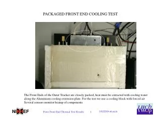
FETS main components: • High brightness H- ion source. • Magnetic Low Energy Beam Transport (LEBT). • High current, high duty factor Radio Frequency Quadrupole. • Very high speed beam chopper. • Comprehensive diagnostics.
Dan Faircloth Peter Savage Chris Thomas Ion Source FETS will use the world leading ISIS H- Penning type ion source. This source routinely produces >40 mA in 250 s pulses at 50 pps. An extensive ongoing development programme will increase the duty factor and fully characterise the beam.
1.2ms 35mA beam at 50Hz Recent work has succeeded in producing 1.2 ms, 35 mA pulses at 50 pps.
A series of Oxford university student projects has resulted in energy spread measurements of the H- beam.
A pepper-pot system will measure the beam emittance as a function of position downstream of the source. Provides data for the LEBT design and information about space charge/neutralisation.
John Back Magnetic LEBT A 3 solenoid magnetic LEBT is being designed, based on the one successfully used on the ISIS RFQ pre-injector upgrade. An electrostatic LEBT has been rejected due to the close proximity of the caesiated ion source.
An initial beam optics design has been completed. Further optimisation will be carried out based on the results of the pepper-pot measurements.
Aaron Cheng Ajit Karup Alan Letchford Peter Savage 324 MHz RFQ A 0.5 m, 324 MHz 4-vane RFQ cold model design is almost complete. Machining tests have been successfully completed in Aluminium. The cold model contains all the significant features of the final 4 m long design. Cold model production will start very soon – delayed by machine tool problems at IC. Tests of the brazing technique were completed successfully.
Final optimisation of some details – such as the vane end cut-aways – is all that remains to be done. A 4 rod RFQ design is also being investigated.
A computer controlled bead pull system is under development to perform cavity field measurements on the cold models
An initial beam dynamics design has been completed for the FETS 324 MHz RFQ. Negligible emittance growth and 94% transmission for a 60 mA beam. Further optimisation is expected.
Giulia Bellodi Mike Clarke-Gayther Frank Gerigk Ciprian Plostinar High speed beam chopper A novel tandem chopper technique has been developed at RAL to overcome the conflicting requirements of fast rise time (< 2ns) and long flat-top (up to 100 s). A ‘fast’ chopper creates a short, clean gap in which a ‘slow’ chopper can switch on. The fast pulser is limited in flat-top but can switch between bunches. The slow pulser cannot switch between pulses but can generate the required flat-top.
A state of the art fast switch developed for RAL has achieved ±1.4 kV with rise and fall times less than 2 ns.
A trimmable helical structure with adjustable delays replaces the more ‘typical’ meander line. Adjustable L-C trimmer Adjust cable lengths to change delay
Three chopper line optics designs are under investigation. A short line keeps the emittance growth low but makes chopping harder and requires some challenging technology. A long line is ‘easier’ but controlling the emittance is more challenging. The short ‘ESS’ solution will require novel, compact, high gradient quadrupoles and DTL-like cavities. Hybrid permanent and electromagnetic quads are being investigated.
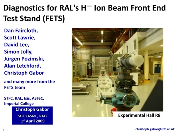
- - - - - - - Charge separation Photo detachment Detection of distribution I(t,y)-> profile, long. e (TOF) “no” momentum transfer magnetic dipole - - - - - - - - - - - - - - - - - - - I(t,y,x)-> 2 D profile, transv. e David Lee Jürgen Pozimski (Christoph Gabor) Diagnostics Accurate diagnostics are essential for FETS to be successful. In addition to more usual diagnostic devices, non-destructive laser stripping techniques will be employed.
IAP Frankfurt laser transverse emittance measurement system.
Timescales A fairly aggressive schedule has been set: Ion source commissioned by beginning 2007. LEBT commissioned by end 2007. RFQ commissioned by end 2008. MEBT/Chopper commissioned by mid-end 2009. Diagnostics commissioned in parallel. A tough timescale to meet for our small group and dependent on appropriate resources.