Download

1 / 16
160 likes | 264 Views
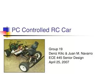
Network RC Car. Seth Schwiethale James Crosetto James Ellison. C ar’s I nput. square pulse of 1.0-2.0 ms, repeats every 20 ms It is the same for both steering and acceleration width of the pulse determines the direction/speed w / 1.5 ms as the nominal center

E N D
Network RC Car Seth Schwiethale James Crosetto James Ellison
Car’s Input • square pulse of 1.0-2.0 ms, repeats every 20 ms • It is the same for both steering and acceleration • width of the pulse determines the direction/speed w/ 1.5 ms as the nominal center • the amplitude of the pulse is from the reference level of the Vcc (5v)
Camera’s Output • 1 “alarm” output • max activation is 100 times/sec (increments of 10 ms)
The Problem • Camera’s output can’t produce a 20ms PWM signal that is highbetween 1-2ms • Car cannot be driven by Camera directly • need something that modifies the output signal of the camera so it can be used by the car
The Solution • Using a microprocessor (MC9S12DP256) • has a clock signal rate of 24MHz • has registers for a Pulse Width Modulator and an Enhanced Capture Timer • Signal from the camera can be varied between 10-110ms for speed and 120-220ms for steering
Pulse Width Modulation camera’s output microprocessor car’s input
Pulse Width Modulator • used to create correct output signal • uses CPU clock signal to generate signal lengths • current signal is 24MHz and we need a 50Hz (20ms) signal (Factor of 480000!)
Determining the Output Signal • Initializing the Pulse Width Modulator
Modifying the Clock Frequency • The pulse width modulator uses registers to decrease the frequency of the clock signal before it is used as an output signal • Two output signals can be generated from the clock signal Allows for finer control of signal
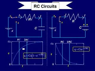
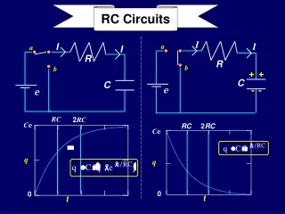
Setting the Period • The periods of both SA and SB need to be 20ms
Setting the Duty Cycle • The duty cycle (the part of the PWM signal that is high) needs to be 1-2ms in length • Initialized to 1.5 ms Notice the difference!
Enhance Capture Timer • Used to trigger interrupts • Set up to trigger an interrupt every time a signal goes high or low on an input port (TCTL4 and TIE)
Counting • Timer Register (TCNT) is incremented every clock cycle (24MHz clock = 24 million times per second) • Clock slowed to 187.5 KHz • TCNT is 16-bit register (0-65535) • Overflows about every 1/3 second (65535/187500) • Never overflows more than once per input signal from camera