Download
1 / 17
180 likes | 510 Views
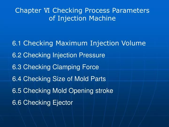
Chapter Ⅵ Checking Process Parameters of Injection Machine. 6.1 Checking M aximum I njection V olume 6.2 Checking I njection P ressure 6.3 Checking C lamping F orce 6.4 Checking Size of Mold Parts 6.5 Checking M o ld Opening stroke 6.6 Checking E jector.

E N D
Chapter Ⅵ Checking Process Parameters of Injection Machine 6.1 Checking Maximum Injection Volume 6.2 Checking Injection Pressure 6.3 CheckingClamping Force 6.4 CheckingSize of Mold Parts 6.5 Checking MoldOpening stroke 6.6 CheckingEjector
6.1 Checking Maximum Injection Volume The actual injection volumeshould be less than 80% injection machine’s maximum injection volume injection volume shown by volume : V ≤ 0.8Vm where, V - Total volume of plastic parts (plastic parts + gating system) V m - Maximum injection volume ofinjection machine (cm3)
6.1 Checking Maximum Injection Volume The injection volume shown by weight: G ≤ 0.8G m G = p'V where, G - The total weight of plastic parts (plastic parts + gating system) G m - The maximum injection volume of the injection machine (g) p'- Plastic barrel temperature and pressure density (g/cm3)
P iwill be affected by the gating system, the resistance of the cavity, the mold temperature and other factors. When P iis too big: lager flash, demolding difficult, poor surfacequality, and big internal stress When P i is too small: can not successfully filled cavity, form inadequate Check the Rated injection pressure of injection machine can meet the required pressure or not P n ≥ P i Where, P i - The requiredpressure of plastic molding injection P n - The nominal injection pressureinjection machine 6.2 Checking Injection Pressure
The clamping force is the maximumforce of the clamping device applied to the mold Fc≥q·Ap Where, F c–The nominal clamping force of injection machine (N) A p – The total projected area of the plastic pieces and pouring system in the parting surface(mm2) q - The average pressure of the plastic melt cavity (MPa) 6.3 CheckingClamping Force
Nozzle size locatinghole size Rod spacing Mold closed thickness Mounting screw hole size 6.4 CheckingSize of Mold Parts
6.4 CheckingSize of Mold Parts 1.Nozzle size The spherical radius of gate sets R and the spherical radius of nozzle front end R0 Nozzle diameter d0 and gate sets small sidehole diameter d Relationship: d = d0 + (0.5-1) mm R = R0 + (1-2) mm
6.4 CheckingSize of Mold Parts 2.locatinghole size h: small mold, take (8-10) mm Largemold,take (10-15) mm
6.4 CheckingSize of Mold Parts 3.Rod spacing Dimensions of one mold should be less than the rod spacing of the injection molding machine to ensure that the mold can be installed on the injection machine work table. The relationship between mold size and rod spacing of the injection machine
6.4 CheckingSize of Mold Parts 4.Mold closed thickness Hmax≥Hm≥Hmin
6.4 CheckingSize of Mold Parts 5.Mounting screw hole size Mold lighter weight using plate fixed Mold heavier weight using screw fixed
6.5 Checking MoldOpening stroke maximum stroke of mold opening of injection machine(S) is independent of mold thickness (Hm) Single-parting surface mold: S> = H1 + H2 + (5 ~ 10) mm Double-parting surface mold: S> = H1 + H2 + a + (5 ~ 10) mm Checking opening stroke of single-parting mold Checking opening stroke of double-parting mold 1-Fixed mode 2-Flow plate 3-Dynamic model 1-Fixed mode 2-Dynamic model
6.5 Checking MoldOpening stroke maximum stroke of mold opening of injection machine(S) is independent of mold thickness (Hm)
6.5 Checking MoldOpening stroke Single parting surface mold: S0 = Hm + [H1 + H2 + (5 ~ 10)] Double parting surface mold : S0 = Hm + [H1 + H2 + a + (5 ~ 10)] Stroke checking of hydraulic clamping part
6.5 Checking MoldOpening stroke maximum mold opening stroke of side parting core-pulling mechanism (S) When H4 in> H1 + H2, S = H4 in (5 ~ 10) mm When H4 in <H1 + H2, S = H1 + H2 + (5 ~ 10) mm
center eject Sides dual mechanical eject center hydraulic eject and side dual mechanical ejector center eject and auxiliary fuel tank 6 .6 CheckingEjector classification of ejector :
Thinking and Practice calculation of injection machine Vertical injection machine Horizontal injection machine Right-angle injection machine XS-ZY-500:means the injection machine with a maximum injection volume of 500cm3 XS:Plastic molding machine Z:Injection machineY:Screw S-ZY-190/90:The injection volume is 190cm3、Clamping force is 90t SYS-30:means the vertical injection machine with a injection volume of 30g