Download
1 / 44
440 likes | 686 Views
Portable Solar Power Supply. Group V: David Carvajal Amos Nortilien Peter Obeng. September 11, 2012. Project Definition. Mobile harnessing of solar energy Store this energy into a battery Supply the stored energy when desired . Project Overview. Solar Panel Solar Tracking

E N D
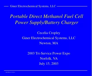
Portable Solar Power Supply • Group V: • David Carvajal • Amos Nortilien • Peter Obeng September 11, 2012
Project Definition • Mobile harnessing of solar energy • Store this energy into a battery • Supply the stored energy when desired
Project Overview • Solar Panel • Solar Tracking • Maximum Power Point Tracking (MPPT) • Charge Controller • DC/DC Converter • DC/AC Inverter
Goals and Objectives • Harvest solar energy • Convenient mobile power • Lightweight • Provide Power for broad range AC and DC devices
Portable Solar Power SupplyBlock Diagram Power from Solar Panel Microcontroller (MPPT) LCD Display Charge Regulator 12 V Lead Acid Battery Provision of AC and DC Power Microcontroller and Motor (Solar Tracking) Solar Panel Mount
Specifications and Requirements • Convert 12 V DC to 120 V AC at 60Hz • Capable of supplying 5 V DC at 500mA for USB outputs • The efficiency (Input power from solar panel to output power from outlet devices) should be at least 90 percent • An MPPT algorithm that works very well to keep the solar panel operating at its maximum power point (MPP) • Horizontal rotation for solar panel mount (solar tracking)
Monocrystalline Solar Panel • 50 Watt Solar Panel • Monocrystalline Photovoltaic Solar Panel • Up to 50 Watts (power) • Up to 2.92 Amps (current) 24 in. 21in.
Solar Angle of Incidence • Depends on the geographic location and time of year. • The fixed angles are dependent of the seasons. • Multiple solar angle calculators can be found online.
Photoresistor • A sensor whose resistance varies with light intensity • Decreases in resistance as the light intensity increases • The resistance must be converted to a voltage
Solar Tracker 2 photocells IC comparator Resistors and Diodes 2 limit switches 2 relays Terminal connectors Powered by 12VDC Single axis tracker 12VDC motor Solar panel mount 2.5 in. 2.75 in. 2 in.
DC to DC Converter • LM3481 • Input Voltage from 3.0 V to 48V • Outputs 5V, 1 A • Current divider to have output of 500 mA • 84% efficiency • Switching frequency: between 100kHz and 1 MHz
DC to DC converter • LT3502 • Input Voltage from 3.0 V to 40V • Outputs 5V, 500 mA • 87% efficiency • Switching frequency: 2.2MHz
Battery Specification Convenience • Manufacture:Battery Mart • Type: Sealed Lead Acid Battery • Voltage Output: 12 Volt • Capacity: 35 Ah • Size: 7.65 L x 5.25 w x 7.18 h in. • Cost : Donated • Weight: 29.00 Pounds • Battery Life: 100,000 hours • Deep Cycle Sealed • Long Service Life • Long Shelf Life • Wide Operating Temperature Ranges (-40°C to +60°C ) • No Memory Effect • Recyclable
Maximum Power Point Tracking (MPPT) • The current and voltage at which a solar module generates the maximum power • Location of maximum power point is not known in advance • Modifies the electrical operating point of a solar energy system to ensure it generates the maximum amount of power. • Finding the current or voltage of the solar panel at which maximum power can be generated • Improves electrical efficiency of a solar energy system
Maximum Power Point Tracking (MPPT)Algorithms Perturb and Observe: • Most commonly used because of its ease of implementation • Modifies the operating voltage or current of the photovoltaic panel until maximum power can be obtained Incremental Conductance: • Take advantage of the fact that the slope of the power-voltage curve is zero at the maximum power point - The slope of the power voltage curve is positive at the left of the MPP and negative at the right of the MPP • MPP is found by comparing the instantaneous conductance (I/V) to the incremental conductance (ΔI/ΔV) • When MPP is obtained, the solar module maintains this power unless a change in ΔI occurs.
Maximum Power Point Tracking (MPPT)Algorithms Hill Climbing Algorithm (Implemented in this project): • Uses an iterative approach to find the constantly changing MPP • The power-voltage graph in the figure to the right resembles a hill with the MPP at the summit • Microcontroller measures the watts generated by the solar panel • Controls the conversion ratio of DC/DC converter to implement the algorithm
Charge Regulator • DC/DC Converter (Buck) • Built on ArduinoProtoshield. • Changes the solar panel’s higher voltage and lower current to the lower voltage and higher current needed to charge the battery. • Controlled by PWM signal that switches the MOSFETS at 50kHz • Prevents battery from discharging at night • Measures battery and solar panel’s voltage
Charge ControllerCurrent Sense Resistor and High Side Current Sense Amplifier
Charge ControllerSwitching MOSFETS and Blocking MOSFET, and MOSFET Driver
MicrocontrollerArduinoDuemilanove Specification: Function: • Processor: ATmega168 • Operating Voltage: 5 V • Digital I/O Pins: 14 (6 provides PWM output) • Analog Input Pins: 6 • DC Current per I/O Pin 40mA • Flash Memory: 16KB (2KB is used by bootloader) • SRAM: 1 KB • EEPROM: 512 bytes • Clock Speed: 16MHz • Controls Charge Controller to Optimize battery charging • Displays status of the portable solar power supply on LCD display
LCD Display Pin connections
Pure sine wave InverterSpecifications • 95% of Efficiency • Output voltage of 120V AC at 60 Hz • Power rating of 500 W
InverterInversion Process • Stepping up the low DC voltage to a much higher voltage using boost converter • Transforming the high DC voltage into AC signal using Pulse Width Modulation Inverter
Block Diagram AC Output Signal MCU Signal Generation Voltage Regulator MOSFETs Drivers H-bridge DC Input High DC Voltage
High Voltage DC/DC ConverterSpecification • Feed the high side of the H-bridge • Efficiency of 90% • Isolated voltage feedback • Cooling passively
Pulse Width Modulation Method of generating AC Power in Electronic Power Conversion through: • Simple Analog Components • Digital Microcontroller • Specific PWM Integrated Circuits
H-Bridge Circuit • Circuit that enables a voltage to be across a load • Consists of 4 switches, MOSFETS
H-Bridge CircuitControl of the Switches Table 4.4.4-1: Switches Position and Load Sign
MOSFET Driver • To switch a low voltage on the device • Bootstrap Capacitor
MicrocontrollerMSP430F449 Specification Functionality • Frequency: 8 MHz • Flash: 60 KB • SRAM: 2048 KB • Comparator: Yes • Generate signals for the MOSFET drivers • Control the PWM • Provides easier feedback to control power
Problems • Microcontroller MSP430 • How efficient it will handle and control the pulse width modulation • Mechanical portion of the project • Solar Panel Mount
Total Spent $323.93