Download
1 / 37
430 likes | 788 Views
Infiltration Trenches. Dave Briglio, P.E. MACTEC Mike Novotney Center for Watershed Protection. Diversion for WQ v Stilling pool and spreader Sedimentation channel or chamber Overflow weir or protective covering layer Infiltration trench with gravel Overflow & outlet. Pavement edges

E N D
Infiltration Trenches Dave Briglio, P.E. MACTEC Mike Novotney Center for Watershed Protection
Diversion for WQv Stilling pool and spreader Sedimentation channel or chamber Overflow weir or protective covering layer Infiltration trench with gravel Overflow & outlet Pavement edges < 5 acres drainage ≤ 2 day drawdown No hotspot application 2-4 feet to water table – close may need to do mounding computation Setbacks for groundwater protection WQv diverted into trench Major ComponentsInfiltration Trench
Compute WQv and if applicable Cpv Screen site Screen local criteria Compute Qwq Size diversion Size filtration area Size pretreatment area Size overflow 24-48 hour drawdown Fill time estimate of 2 hours is normal Porosity = 0.32 If pretreatment facility size for 25% WQv Design Steps
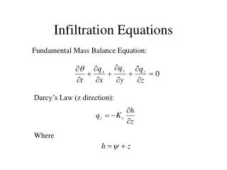
n=0.32 d=depth in feet k=percolation rate (in/hr) T = fill time = 2 hrs. Gravel Trench Volume A = WQv/(nd+kT/12) = WQv/(0.32d+k/6)
Gravel Trench Area Per Acre Percent Impervious k=1 in/hr (sandy loam), n=0.32, T=2 hrs
Erosion & Sediment Control Considerations • Ensure sediment is trapped before entering filter area • Installation sequencing is important • After adjacent areas are stabilized • Converted temporary sediment basins (Sd3) • Provide pretreatment with sediment basin or filter strip
An example of Infiltration trench design Taken from Appendix D4
Step 2. Calculate WQv peak discharge (Qwq)WQv = 8102 cf, P = 1.2”, Qwv = WQv/Area = 0.74”CN = 95…Ia=(1000/CN-10)…Ia/P…qu…Qwq • Back out curve number • Calculate unit peak discharge using SCS simplified peak figures • Calculate peak discharge as: Qwq = 2.2 cfs
Step 3. Size the infiltration trench • n=0.32 • D= 5 feet • k=1 (in/hr) • T = 2 hrs. • A = 8,102 (32.2x5)+(1x2/12) • A = 4,586 sf • Max. width = 25 ft • L = 4,586/25 = 183 ft A = WQv/(nd+kT/12) = WQv/(0.32d+k/6) • n=porosity • d=depth in feet • k=percolation rate (in/hr) • T = fill time
Step 3. Size Point A flow diversion structure Q25 = 17cfs, WQv= 2.2 cfs 2/3 of the flow to Point A (1/3 to Point B) Point A: Q25= 5.7cfs, WQv = 0.73 cfs Design orifice for low flow (0.73 cfs) • Set max. head = 1.5’ • Q=CA(2gh)1/2…C=0.6…A=0.12 sf (4”dia.) …use 6-inch pipe w/ gate valve
Step 3. Size Point A flow diversion structure Q25 = 17cfs, WQv= 2.2 cfs 2/3 of the flow to Point A (1/3 to Point B) Point A: Q25 = 5.7cfs, WQv = 0.73 cfs Design weir for 25-yr flow (5.7 – 0.73 = 5cfs) • Set max. head = 1.0’ • Q=CLH3/2…C = 3.1…L=1.6 ft
Coastal Challenges… See Handouts for LID Practices…
Coastal Challenges… See Handouts for LID Practices…
Coastal Challenges… See Handouts for LID Practices…
Coastal Challenges… See Handouts for LID Practices…
Coastal Challenges… See Handouts for LID Practices…
CSS Design Credits • 7.4 Better Site Planning Techniques • 7.5 Better Site Design Techniques • 7.6 LID Practice • 8.4 General Application BMPs