Download
1 / 25
250 likes | 264 Views
This paper presents the thermal analysis and heat load measurements for the accelerator prototype modules of the European XFEL. It discusses the heat transfers by current leads, power couplers, support posts, and multilayer insulation. The results and conclusions are provided along with references.

E N D
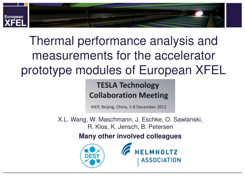
Thermal performance analysis and measurements for the accelerator prototype modules of European XFEL X.L. Wang, W. Maschmann, J. Eschke, O. Sawlanski, R. Klos, K. Jensch, B. Petersen Many other involved colleagues
Overview • Introduction. • Thermal analysis. • Heat load measurements. • Results and discussion. • Conclusions. • Sources and references.
Introduction • Based on The TESLA/TTF-Type III design. • 10 Hz pulsed operation. • One Cryomodule consists of: 8 1.3 GHz 9-cell Nb cavities (2 K), 1 magnet package (2 K), two thermal shields (5/8 K and 40/80K), 8 main RF couplers, 3 support posts. • 12 m length and 7.8 t total weight.
Thermal analysis Heat transfers by • Current leads. • Power couplers. • Support posts. • Multilayer insulation (MLI).
Heat transfer by current leads • Conduction cooled current leads with two heat sinks and developed by CERN. • Heat transfer mechanisms: • Conduction through brass and copper; heat generated by current and material properties changes with temperature. • Negligible axial conduction through SS, Kapton tube and the helium gas and contact thermal resistances. • A numerical model is developed by using Matlab. • A analytical model is used to validate numerical results in appropriate limits. 40/80K Heat sink Current leads 5/8K Heat sink
Heat transfer by current leads Design parameter of the current leads Db: Diameter of the brass, tcu: Thickness of copper plating. Comparisons from analytical and numerical models (One lead, constant thermal conductivity and electrical resistivity) • A: Analytical solutions • N: Numerical solutions • ‘1’ and‘2’ denotes respectively the solutions with neglecting and considering heat conduction of the brass • CERN A and DESY A1 fit very well. • Heat conduction through the brass had been neglected in CERN design. • The analytical and numerical results have a good agreement.
Heat transfer by current leads Heat loads by current leads Ts: Shield temperature, Ti: Thermal intercept temperature • 2 K static one: ~1 W 2 K dynamic one: ~ 0.1 W • 5/8 K static one: ~2-3 W 5/8 K dynamic one: ~0.4-0.9 W • 40/80 K static one: ~10-12 W 40/80 K dynamic one: ~3-4 W
Heat transfer by power couplers • Eight power couplers in one module. • Conductors made up of SS tubes coated by the copper. • Two thermal sinks at 5/8 K and 40/80 K levels. • Heat transfer mechanisms: • Conduction through the inner and outer conductors. • Heat generation by the RF power coupler. • Radiation heat from the antenna to 2 K and 5/8 K levels. • The numerical model is similar with that of current leads. 300K Flange 40/80K heat sink Cavity 5/8K heat sink Outer warm conductor Antenna Inner warm conductor 2K Flange 40/80K shield 5/8K shield Courtesy D. Kostin
Heat transfer by power couplers Basic parameters of the power coupler Comparisons with DESY previous model (M. Dohlus, Proc. LINAC 2004) (One coupler, static, qcp1: Present, qcp2: Previous ) The other comparison with Fermi model (T. Peterson, TESLA report, 1993) 2 K level, identical parameters, error of about 10%.
Heat transfer by power couplers Static Heat loads by power couplers • 2 K static one: ~0.5 W • 5/8 K static one: ~1-3 W • 40/80 K static one: ~16-18 W 5/8K shield Copper braids 40/80K heat sink 5/8K heat sink Coupler
Heat transfer by support posts • Three support posts in one module. • Two thermal sinks at 5/8 K and 40/80 K levels. • Heat transfer mechanisms: • Conduction through G-10 tube. • Radiation heat from the MLI (Negligible) • The numerical model is similar with that of the current leads. • The analysis model is used to validate the numerical results. • Cryocomp properties version 3.0 provides three kinds of G-10 with various conductivities depending on the angles between the thermal gradient and the fiber direction. • The maximum conductivity G10 is taken.
Heat transfer by support posts Comparisons with INFN previous model (S. Barbanotti, INFN/TC-08-01) (One support post, qA: DESY analytical, qN: DESY numerical ) Heat loads by support posts • 2 K: ~0.5 W • 5/8 K: ~1-3.5 W • 40/80 K: ~34-37 W
Heat transfer by the MLI • 30 layers at 40/80 K and 10 layers at 5/8 K. • Surface areas: 30.9 m2 at 40/80 K and 26.4 m2 at 5/8 K. • Heat transfer mechanisms: • Conduction through the solid. • Radiation heat. • Conduction through residual gas (Negligible P<10-3 Pa). • Difficulty to calculate accurately. • Reviewed empirical results from CERN and NASA.
Heat transfer by the MLI Empirical results of heat fluxes 2 K: Negligible, 5/8 K: 0.05 W/m2, 40/80 K: 1.5 W/m2 (many openings). Empirical formulas adapted to empirical heat fluxes (T. Nast, Multilayer insulation system) Heat loads by the MLI • 2 K: - • 5/8 K: ~0.3-1.3 W • 40/80 K: ~46-49 W
Thermal analysis summary Others including heat loads from HOM absorbers, cablings, etc. is extracted from refrigerator budget, where 2 K: 0.4 W, 5/8 K: 1.7 W, 40/80 K: 5.4 W. • 2 K: 2.1W. • 5/8 K: 6-12W strongly depending on the 40/80 K shield temperatures. • 40/80 K: 110-120W slight effected by the 40/80 K shield temperatures.
Heat load measurements • Tested at Cryomodule test bench (CMTB). • Four modules and seven measurements plus dummy test. • PXFEL2_1: New MLI at 40/80 K shield. • PXFEL3 (B): Disconnected the 40/80 K thermal intercept of current leads. • PXFEL2 (B): T sensors at sliding muff range calibrations. • Dummy test: pure heat load of CMTB without the module.
2 K: Measure the mass flow rate of the evaporated helium in an enclosed space. Calorimetric flow meter at room temperature (0-1 g/s). Heater calibrations. Accuracy of less than 10 %. Methodologies and instrumentation
Methodologies and instrumentation 5/8 K and 40/80 K: Enthalpy balance For Helium For Cold mass for cross check Cold mass: AL of 388 kg and helium of 0.5 kg. Averaged T increase: 58.9 K to 66.3 K within 2 hours. Heat load of 94 W Pure heat load of 99 W At 40/80 K
Methodologies and instrumentation • 40/80 K: Pt1000 (on tube installation), Venturi flow meters. • Warm flow input to change outer shield T from 40-80 K. • 5/8 K: CernoxTM (in tube installation), Ventur flow meter. • Heater calibrations for all circuits. • Accuracy of less than 10 %.
Results and discussion Outer shield T≈40 K 14 W • 2 K: PXFEL1 quite higher than others. Differences from others (due to installation skill of current leads) • 5/8 K: Reasonable agreements. Strongly effected by outer shield T. 40/80 K: Could fit well with assumption of 1 W/m2 through the MLI for PXFEL2_1. 5/8 K: PXFEL3 (B) higher than others. • 40/80 K: ∆Q=14 W from PXFEL3. Calculated: 12 W, fit reasonably • 40/80 K: PXFEL3 (A) higher than others. • 40/80 K: PXFEL2_1 lower than others.
Results and discussion PXFEL3 end cap side PXFEL3 feed cap side Tuner misalignment causes higher 40/80 K heat load of PXFEL3 (Guess) New MLI at 40/80 K shield in PXFEL2_1 improves the thermal performance (TBC) Layout of current leads causes quite high 2 K heat load of PXFEL1 (Confirmed) PXFEL2_1
Conclusions Static heat load summary of PXEFL modules XRB: XFEL refrigerator budget, XRC: XFEL refrigerator capacity • 40/80 K: 100-120 W depending on the performance of MLI. • 5/8 K: 6-12 W depending on the outer shield temperatures. • 2 K: 3.5-6 W depending on the installation skills of current leads. • Measured and calculated values have a good agreements at 5/8 K and 40/80 K. • Big deviation at 2 K caused by underestimation of cabling heat load and the installation skills of current leads. • Specified refrigerator capacity still could cover the heat load at 2 K and 40/80 K (Even come to limit) and have enough margin at 5/8 K.
Sources and references B. Petersen, Some fundamentals of cryogenic and module engineering with regard to SRF technology, SRF2007 Tutorial Program T. Peterson, What’s inside a TESLA Cryomodule, Proton driver meeting, 2005 C. Pagani, Cryomodule design, assembly and alignment, SRF 2005 N. Ohuchi, Fundamentals of cryomodule, SRF2009 Tutorial Program T. Peterson, ILC cryogenic systems reference design, CEC 2007 T. Nast, ‘Multilayer insulation system’ in Handbook of cryogenic engineering, 1998 Thomas M. Flynn, Cryogenic Engineering, Second Edition, 2005 S. D. Augustynowicz, Cryogenic Insulation System for Soft Vacuum, CEC2000 L. Mazzone, Measurement of multi-layer insulation at high boundary temperature, ICEC19 L. Dufay, A large-scale test facility for heat load measurements down to 1.9K, CEC2002 J. Fesmire, Performance characterization of perforated multilayer insulation blankets, ICEC19, 2002 C. Darve, Thermal performance measurements for a 10-meter LHC dipole prototype, LHC-Project-Note-112, 1997 A. Ballarino, Conduction-cooled 60A resistive current leads for LHC dipole correctors, LHC project report 691, CERN, 2004. A. Ballarino, Current leads for the LHC Magnet System, MT17, Switzerland, 2001 M. J. White, Numerical model for conduction cooled current lead heat loads, Presented to CEC 2011 Cryocomp properties version 3.0, Cryocomp, Eckels Engineering, 1997 NIST Cryogenic Materials Database, http://cryogenics.nist.gov/MPropsMAY/Polyimide%20Kapton/PolyimideKapton_rev.htm HEPAK, Cryodata, Inc., Version 3.40 Gregory Nellis, Sanford Klein, Heat transfer, Cambridge university press, 2009 M. Dohlus, TESLA RF power coupler thermal calculations, LINAC 2004, Germany T. Peterson, FERMILAB input coupler heat calculations, 1993, TESLA report 1993-37 S. Barbanotti, Traction tests for the qualification of the TTF/ILC composite support posts, INFN, Italy, 2008 Y. Bozhko, XFEL Cryomodule Test Bench, ICEC21, 2006 N. Ohuchi, SCRF Cryomodule R&D in KEK-STF, 2nd Asia ILC R&D seminar, 2008 N. Ohuchi, Experimental study of thermal radiation shield for ILC Cryomodule, ICEC23 N. Ohuchi, Study of thermal radiation shields for the ILC Cryomodule, Presented to CEC 2011
End Thank you for your attention!