Download
1 / 27
270 likes | 478 Views
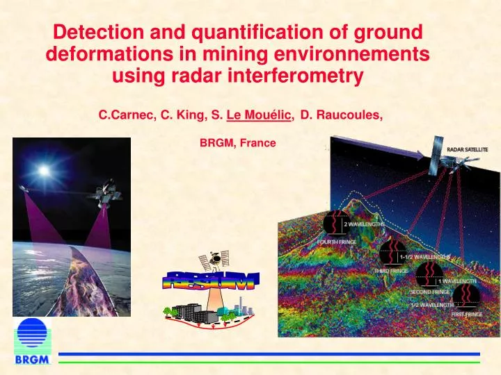
RESUM. Detection and quantification of ground deformations in mining environnements using radar interferometry C.Carnec, C. King, S. Le Mouélic , D. Raucoules, BRGM, France. Plan. Introduction Radar interferometry Examples Conclusion and perspectives.

E N D
RESUM Detection and quantification of ground deformations in mining environnements using radar interferometryC.Carnec, C. King, S. Le Mouélic,D. Raucoules,BRGM, France
Plan • Introduction • Radar interferometry • Examples • Conclusion and perspectives
Ground deformations : A parameter to integrate into a global environnemental monitoring system • Industrial exploitation of natural ressources : mining activity, gaz stocking (natural ou artificial), oil industry, geothermal field • Underground urban works • Underground water pumping… • Natural processes • - Potential damages to the existing overlying buildings • - Instabilities to be considered for land use planning
Problem... RESUM Detection and quantification of ground deformations • Where? • When ? • How do they evolve (space /time) ? …and solutions • Conventional • - levelling • - GPS,... • Satellite observations Aménagement et Risques Naturels
Radar interferometry - principles
Satellite Radar interferometry : principle Backscattered signal Radar pulse Amplitude(backscattering coefficient) : roughness, dielectric properties Phase: distance dist Fintrinsic is random can be eliminated by difference
Differential interferometry : principle DEM Phase difference between two acquisitions : interferogram, or difference of distances (modulo 2p ) B F = forbit +fellips + ftopo +fmvt +fatmos + noise Surface deformations (accuracy ~cm) Orbital parameters
geophysical applications Earthquakes Volcanology Glaciology Landers - 1992 - Magnitude 7.5 (JPL) Piton de la Fournaise Volcano périod 1996-1998 (CNES) Glacier evolution in Antarctique (JPL)
Applications in mining environnements- Framework : RESUM project - Examplesof results
RESUM RESUM project : Urban and Mining subsidence network Partners Spatial Agency (*) CNES 4 public organizations BRGM, IGN, LCPC-CETE 1 National SchoolECPEcole Centrale de Paris 3 small business KINOA (INSAR processing) companies TRE Telerilevamento Europa(INSAR) Magnitude (microsismic surveys) Final end-users PMEMagnitude 2 IndustriesCdFCharbonnages de France GdF Gaz de France (*)support from ESA : provides ERS data (for research purpose)
Example 1 : inflation caused by water recharge in an abandoned mine (Montceaux-les Mines, France) Period 12/1995 and 12/1998. 0 2
Example 1 Inflating mean velocity between 1995 and 1998 estimated by radar interferometry The study has shown that the deformation (up to 7.5 cm) occurs beyond the limit of the exploited area 0 1.2 2.5 (cm/yr)
Example 2 : subsidence caused by underground mining (Gardanne, France) h=1100 m 1992 1994 1995 Carnec and Delacourt, 1999 • The subsidence bowl migrates with the advance of the coal working face
Example 3 : subsidence over a salt exploitation Period 1993-1999 • InSAR : better evaluation of the amplitude and 3D geometry of the deformation • The position of the levelling network is not optimal • The deformation is not exactly centered on top of the cavity 0 -1.5 -3 (cm) (Raucoules et al., in préparation)
Example 3 • InSAR results compatible with ground truth (Raucoules et al., in préparation)
Exemple 4 : A ground uplift in Paris linked to underground works The observed uplift is correlated in time with the increase of the piezometric level after the end of an important underground construction work Le Mouélic et al, 2002 1 fringe = 3 mm of uplift
Example 5 : Sometimes, it does not work at all !!! (loss of coherence) • Limiting factors : • Vegetation (forest) • Fast evolving phenomenons (collapses)
An alternative for the most difficult cases : the permanents scatterer approach (Ferretti, 2000) • Retrieve the phase history of stable targets (constructions, bare soils) of a site • Powerful, but also time consuming method based on statistical analysis (30 to 60 images required)
Test of this approach in Lorraine (France)(In collaboration with C. Colesanti from TRE) resum
Retrospective analysis of the deformation events 14 november 1996 19 november 1996 Collapse event
Detection of precursor signs First structural disorders constated (18 cm) Begining of the leveling survey
RESUM Conclusion • Radar interferometry : a powerful complementary tool to monitor ground deformations • Best performances in urbanized (or desertic) areas • Ongoing research effort in radar image processing • Overcome the actual limits (loss of coherence) • ERS 2 (no more gyroscope) and Radarsat • New generation of instruments : ASAR/ENVISAT (launched 2002), Radarsat 2, ALOS, ... More information : http://resum.brgm.fr
Performances : • Spatial resolution (pixel) 4 x 20 m • Vertical accuracy : few mm • Revisite cycle 35 j (ERS, ENVISAT), 24 j (Radarsat) • Archive : 1991-2001 (ERS) + ENVISAT (2002 - …) Performances, avantages and limitations • Advantages : • Synoptic view of the deformations (100 x 100 km) • No ground instrumentation (confidentiality) • Days and night observations indenpendently of the cloud cover • Limitations : • Surface variability: • Stability of the targets (forest) • Slow deformations only (max 1/2 frange/pixel) • Atmospheric artifacts (classical interferometry) Poor performances in areas covered by vegetation
Subsidence monitoring by InSAR Problems Origin InSAR contribution Mining activity Monitoring of the impact of in progress · · Monitoring the migration underground mining of the subsidence halo Precise and regular · mesurements of the displacement field · Regular radar acquisitions Mapping surface · · Discretion (no ground deformations from field instruments) leveling data Confidential · Rehabilitation of the area abandoned · Drawing up an inventory of Stability · · mining damages recovering of pressures · Optimization of ground control through water recharge · networks design Dissociation of mining effect · Availability of archive ERS from natural phenomenon · data ( dryness, …) Geodetic network unavailable · Confidential ·
radar interferometry : principe Butte Montmartre Raw Interférogram Interférogram corrected from orbital fringes Interférogramme corrigé de la topographie 1 cycle of color (fringe) = 2,8 cm toward the satellite (3 cm in vertical). accuracy : few mm