Download
1 / 15
150 likes | 333 Views
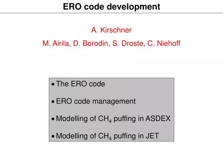
ERO code development. A. Kirschner M. Airila, D. Borodin, S. Droste, C. Niehoff. The ERO code ERO code management Modelling of CH 4 puffing in ASDEX Modelling of CH 4 puffing in JET. The ERO code. 3- dimensional (at present 2D for divertor), Monte Carlo

E N D
ERO code development A. Kirschner M. Airila, D. Borodin, S. Droste, C. Niehoff • The ERO code • ERO code management • Modelling of CH4 puffing in ASDEX Modelling of CH4 puffing in JET
The ERO code 3-dimensional (at present 2D for divertor), Monte Carlo Various experimental geometries are possible (at the moment: TEXTOR, ASDEX, JET, ITER, PISCES, MAGNUM) Plasma-wall-interaction: - physical sputtering, chemical erosion (CH4 or higher hydrocarbons) - C-deposition from background, re-deposition of eroded particles Local particle transport: - ionisation, recombination, dissociation - Ehrhardt/Langer or Janev data for CH4 reaction chain - friction (Fokker-Planck), thermal force, Lorentz force, diffusion D
ERO code management (1) “Main line of development” CVS parallelisation ERO.LIM Variety of versions ERO.DIV ERO.LINEAR Several users and developers: version controlling necessary CVS (Concurrent Versions System) – server at FZJ
ERO code management (2) Development of user friendly interface (“JERO”) in combination with ERO internet webpage
Modelling of 13CH4 puffing in ASDEX (1) B2-Eirene grid of divertor region Z [m] 80° rotation ERO simulation volume R [m]
Modelling of 13CH4 puffing in ASDEX (2) separatrix ERO simulation volume (outer divertor):
Modelling of 13CH4 puffing in ASDEX (3) Plasma parameter (L mode) from B2-Eirene (D. Coster) separatrix
Modelling of 13CH4 puffing in ASDEX (4) Transport of injected CH4 into outer divertor @ s=48mm: sticking assumption for hydrocarbons S = 0 80 mm CH4 CH2 CH CH4 0 0 80 mm CH+ C C+
Modelling of 13CH4 puffing in ASDEX (5) SEP PFR SOL C-Deposition from injected CH4 (@ 48mm) into outer divertor: sticking assumption for hydrocarbons S = 0 local deposition: ~70%, losses to PFR: ~30%
Modelling of 13CH4 puffing in ASDEX (6) Injection of CH4 (@ 48mm and88mm) into outer divertor: Puffing location deeper in SOL: high local re-deposition even if with S = 0!!!
Modelling of 13CH4 puffing in ASDEX (7) Further 13C transport modelling in ASDEX: in co-operation with M. Airila (Helsinki University of Technology)
Modelling of CH4 puffing in JET (1) ZC [cm] ne [cm-3] Te [eV] ZC [cm] -130 -130 -140 -140 -150 -150 -160 -160 -170 -170 -180 -180 220 220 260 260 230 230 240 240 250 250 RC [cm] RC [cm] MkIIA: Standard gas fuelled ELMy H-mode, 12 MW (#44029)
Modelling of CH4 puffing in JET (2) • Zero sticking of hydrocarbons CDy, Ehrhardt-Langer • Location of injection: strike point Profiles of re-deposition for various incoming ion fluxes: Amount of re-deposition: 88% 89% 87% base plate vertical plate
Modelling of CH4 puffing in JET (3) • Zero sticking of hydrocarbons CDy, Ehrhardt-Langer • Location of injection: center of base plate (SOL) Profiles of re-deposition for various incoming ion fluxes: base plate Amount of re-deposition: 76% 72% 66% vertical plate
Modelling of CH4 puffing in JET (4) Summary: re-deposition of injected CD4 and C2D4 Injection at strike point: Injection at center of base plate (SOL): • No significant difference in re-deposition of puffed CD4 and C2D4 • Puffing at strike point: no significant dependence on flux • Puffing at center of base plate (SOL): decreasing re-deposition with increasing flux