Download
1 / 60
2.74k likes | 7.17k Views
FRICTION WELDING. Friction Welding. Lesson Objectives When you finish this lesson you will understand: Continuous Drive Friction Welding & Applications Variables Effecting Friction Welding Variations of friction Welding Process Dissimilar Materials Welded

E N D
Friction Welding • Lesson Objectives • When you finish this lesson you will understand: • Continuous Drive Friction Welding & Applications • Variables Effecting Friction Welding • Variations of friction Welding Process • Dissimilar Materials Welded • Inertia Welding Process & Applications • Learning Activities • View Slides; • Read Notes, • Listen to lecture • Do on-line workbook • View Video Keywords: Friction Welding, Inertia Welding, Forging Pressure, Orbital Friction Welding, Linear Friction Welding, Angular Reciprocating Friction Welding, Radial Friction Welding, Friction Stir Welding
Definition of Friction Welding • Friction welding is a solid state joining process that produces coalescence by the heat developed between two surfaces by mechanically induced surface motion.
Examine the Friction Weld Video on the Web Page Link to Friction Welding Video
Categories of Friction Welding • Continuous drive • Inertia
Workpieces Non-rotating vise Motor Spindle Hydraulic cylinder Chuck Brake Continuous Drive Continuous Drive Friction Welding • One of the workpieces is attached to a rotating motor drive, the other is fixed in an axial motion system. • One workpiece is rotated at constant speed by the motor. • An axial or radial force is applied.
Workpieces Non-rotating vise Motor Spindle Hydraulic cylinder Chuck Brake Continuous Drive Continuous Drive Friction Welding • The work pieces are brought together under pressure for a predeter-mined time, or until a preset upset is reached. • Then the drive is disengaged and a break is applied to the rotating work piece.
Linnert, Welding Metallurgy, AWS, 1994
Continuous Drive Friction Welding Variables(Continuous Drive) • Rotational speed • Heating pressure • Forging pressure • Heating time • Braking time • Forging time
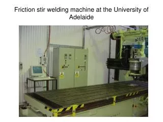
Equipment Direct Drive Machine Courtesy AWS handbook
Continuous Drive Friction Welding Joint Design • The joint face of at least one of the work piece must have circular symmetry (usually the rotating part). • Typical joint configurations shown at right. Tube Rod to tube Rod Tube to disc Tube to plate Rod to plate
Orbital Friction Welding AWS Welding Handbook
Angular Reciprocating Friction Welding AWS Welding Handbook
Linear Reciprocating Friction Welding AWS Welding Handbook
Used to join collars to shafts and tubes. Two tubes are clamped in fixed position. The collar to be joined is placed between the tubes. The collar is rotated producing frictional heat. Radial forces are applied to compress the collar to complete welding. Radial Friction Welding F F F + F F F F F F
Friction Surfacing AWS Welding Handbook
Parts to be joined are clamped firmly. A rotating hardened steel tool is driven into the joint and traversed along the joint line between the parts. The rotating tool produces friction with the parts, generating enough heat and deformation to weld the parts together. Friction Stir Welding Butt welds Overlap welds
Friction Stir Welding Clamping force clamping force Step -1 Step -3 Step -4 Step -2
Friction Stir Welding 900 Corner welds T-section ( 2- component top butt)
Friction Stir Welding Fillet butt welds
Continuous Drive Friction Welding Applications • Frequently competes with flash or upset welding when one of the work pieces to be joined has axial symmetry. • Used in automotive industry to manufacture gears, engine valves, and shock absorbers. • Used to join jet engine compressor parts.
Applications Friction Welded Joints Friction Welded Joint Friction Welded Automotive Halfshaft Courtesy AWS handbook
Applications Friction Welded Joints Camshaft Forging Friction Welded To Timing Gear. Cross Section of Aluminum Automotive Airbag Inflator. Three Welds Are Made Simultaneously Courtesy AWS handbook
Applications Friction Welds A Jet Engine Compressor Wheel Fabricated by Friction Welding Inertia Welded Hand Tools Courtesy AWS handbook
Dissimilar Metals – Friction Welded Aluminum to Steel Friction Weld
Photomicrograph of Aluminum (top) to Steel (bottom) AWS Welding Handbook
Friction Weld Tantalum to Stainless Steel Note: mechanical mixing AWS Welding Handbook
Continuous Drive Friction Weld of Titanium Pipe Ti-6Al-4V-0.5Pd 246 mm diameter 14mm wall thickness No shielding used Center HAZ Froes, FH, et al, “Non-Aerospace Applications of Titanium” Feb 1998, TMS
Radial friction weld of Ti-6Al-4V-0.1Ru Properties in Weld Better than Base Metal Froes, FH, et al, “Non-Aerospace Applications of Titanium” Feb 1998, TMS
Linear Friction Weld Repair of Fan Blades Turbine Fan Compressor Combustor Walker, H, et al, “Method for Linear Friction Welding and Products made by such Method” US Patent 6,106,233 Aug 22, 2000
Friction Welding for Mounting Ti Alloy Rotor Blades Shielding Gas & Induction Pre-heat Weld Nub Force Linear Friction Weld Schneefeld, D,et al. “Friction Welding Process for Mounting Blades of a Rotor for a Flow Machine”, US Patent 6,160,237 Dec 12, 2000
Friction Welding Connector to Imbedded Window Wires Silver Based Ceramic Paint Wire Conductor Glass White, D et al, “Friction Welding Non-Metallics to Metallics”, US Patent 5,897,964 Apr. 27, 1999
Friction Stir Welding – Tool Design Modification Hard Tool Tip Buried in Work Piece Metal Flow Force Travel Speed Midling, O, et al, “Friction Stir Welding” US Patent 5,813,592 Sep. 29, 1998
Friction Stir Welding – Automation Moving Device Elevation Platform and fixture device Friction Stir Welder Mobile Support System Ding, R. et al, “Friction Stir Weld System for Welding and Weld Repair”, US Patent 6,173,880 Jan 16, 2001
Flywheel Motor Non-rotating chuck Workpieces Chuck Spindle Hydraulic cylinder Inertia Drive Inertia Welding Process Description • One of the work pieces is connected to a flywheel; the other is clamped in a non-rotating axial drive • The flywheel is accelerated to the welding angular velocity. • The drive is disengaged and the work pieces are brought together. • Frictional heat is produced at the interface. An axial force is applied to complete welding.
Inertia Welding Where E = Energy, ft-lb (J) I = Moment of Inertia, lb-ft2 (kg-m2) S = Speed, rpm C = 5873 when the moment of inertia is in lb-ft2 C = 182.4 when the moment of inertia is in kg-m2 Eu = Unit Energy, ft-lb/in2 (J/mm2) A = Faying Surface Area
Inertia Drive Inertia Welding Variables • Moment of inertia of the flywheel. • Initial flywheel speed. • Axial pressure. • Forging pressure.
Linnert, Welding Metallurgy, AWS, 1994
Equipment Inertia Welding Machine Courtesy AWS handbook