Download
1 / 76
890 likes | 1.14k Views
Explore GPS co-ordinate systems, calibration importance, steps, software, procedures, site control, relationships, and more in this session. Elevate your surveying skills with key insights and practical knowledge.

E N D
Objectives After this session, you should be able to: • Explain the Co-ordinate systems used in GPS Surveying. • Explain what a calibration is. • Explain the 5 main process steps of a calibration • Recall the software where a calibration can be performed • List the recommended procedures when performing a Calibration. • Correctly site ideal calibration control based on different survey site situations • Explain the required relationship between GPS Base Stations and calibrations • Recall the common base co-ordinate system of a site calibration
First of all what can you remember about the GPS Co-ordinate System?
+Z Z Y X -Y +X ECEF Coordinate System ECEF X = -2691542.5437 m Y = -4301026.4260 m Z = 3851926.3688 m
b b a a Reference Ellipsoid a = semi-major axis b = semi-minor axis H f WGS-84 Ellipsoid a = 6378137.000000 m b = 6356752.314245 m 1/f = 298.2572235630 l
+Z H b Z f Y X l a -Y +X ECEF and WGS-84 ECEF X = -2691542.5437 m Y = -4301026.4260 m Z = 3851926.3688 m WGS-84 f = 37o 23’ 26.38035” N l = 122o 02’ 16.62574” W H = -5.4083 m
What can you remember about the heights you get from GPS and the heights you need to know?
GPS Heights vs. Elevations Earth’s Surface H H e e H e N Ellipsoid N N Geoid e = Orthometric Height H = Ellipsoid Height N = Geoid Height e = H - N
A Calibration • Word refers to several related items in RTK surveying: • File -- the file used on RTK rovers to transform from WGS84 (L,L,H) to local (flat plane, E,N,E) coordinates • RTK field survey -- the survey conducted in the field to determine the mathematical relationship between WGS84 and site (flat plane) coordinate system • What it is literally: the mathematical relationship between WGS84 and site (flat plane) coordinate system
WGS84 NEE Coordinate System This is the GPS calibration! • Converts coordinates from GPS system to our local site (flat plane) coordinate system • Includes datum transformation, map projection, horizontal & vertical adjustment • REQUIRED to work in local (flat plane) coordinates Must Have!!
How do you get from WGS84 ECEF to Easting, Northing and Elevation ?
First Things First • To relate one co-ordinate system to another you need a set of points on the ground that have co-ordinates in both systems. • Therefore you need a set of WGS84 co-ordinates and a set of local Northing, Easting and Elevation co-ordinates. WGS84 Local Site Co-ordinates
Calibration Process • Datum Transformation • Define Projection • Horizontal Adjustment • Vertical Adjustment • Geoid Model (optional)
WGS84 Local Datum Transformation • Usually published parameters • Two basic types: • 3 Parameter • 7 Parameter
3 vs. 7 Parameter 3 Parameter 7 Parameter
Calibration Process • Datum Transformation • Define Projection
Apex of Cone Axis of Cone & Ellipsoid Line of intersection Ellipsoid Intersecting Cone 2 Parallel Lambert Types of Projections Point of Origin Plane Ellipsoid Axis of Ellipsoid Tangent Plane Local Plane Axis of Cylinder Ellipsoid Intersecting Cylinder Transverse Mercator
Calibration Process • Datum Transformation • Define Projection • Horizontal Adjustment (on projected plane surface) • Rotation • Translation • Scale
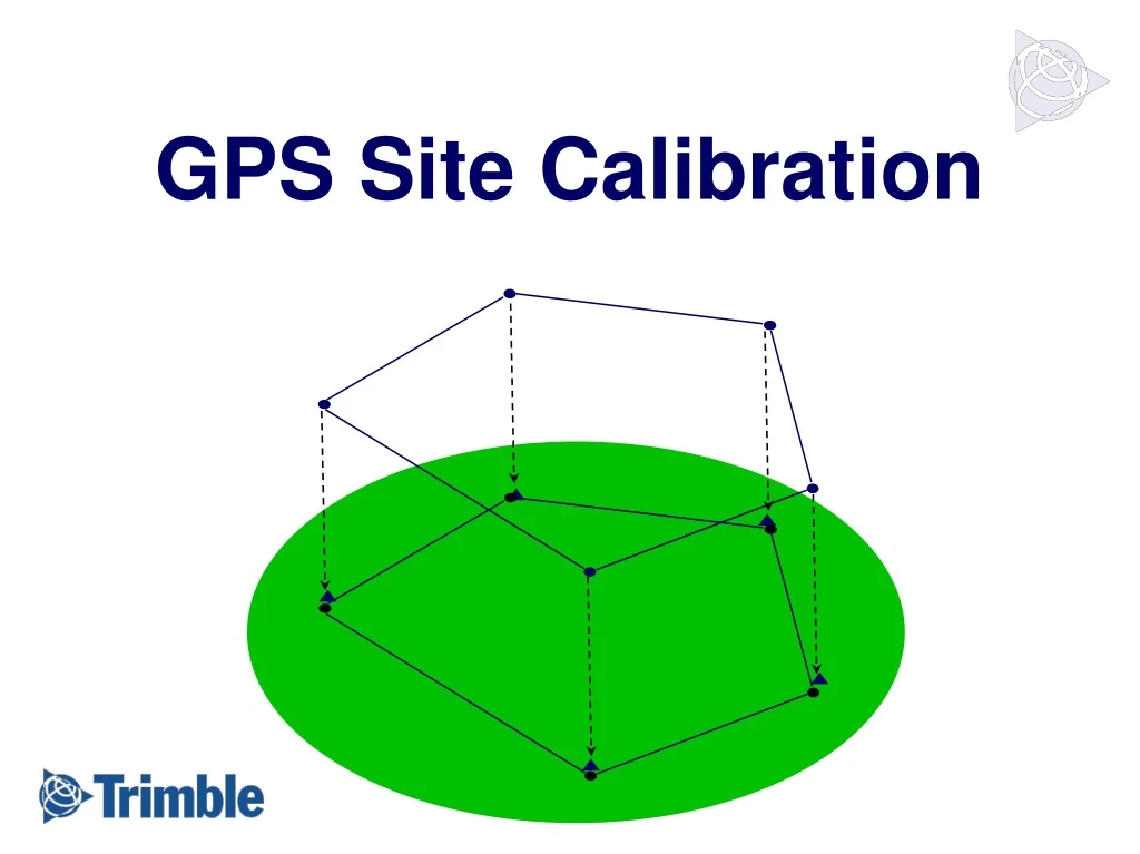
= GPS observation = Control Point Horizontal Adjustment • At least 3 horizontal control points are required • 5 points are recommended
Residual Calibration Results • After the calibration you will obtain a set of calibration results, which consist of residuals. These need to be understood so you know how good the calibration is. • Residuals: The difference between the grid co-ordinate and the GPS co-ordinate after the calibration has been applied.
Residual Calibration Results • Therefore the smaller the residualthe more accurate the calibration parameters are and the better the relationship between the GPS (WGS84 co-ordinates) and the Local Site Easting and Northing co-ordinates.
Residual Calibration Results • You should be looking for residuals ideally less than 20mm, but 30mm may be acceptable. • When you are looking at final co-ordinates your minimum accuracy is: Standard RTK GPS receiver error plus your largest calibration residuals • Your residuals should be spread evenly between the calibration points.
Quick Calibration Summary • Start with Latitude & Longitude, in WGS84, as measured with GPS. • Perform Datum Transformation to obtain Latitude & Longitude in local datum. • Today this is often a system very similar to WGS84, such as ETRS89. • Project local Latitude & Longitude onto a flat predefined plane using a projection. • On the projection perform a Horizontal Adjustment to fit the GPS measured points as close as possible to the Local control points in N,E • Obtain residuals. • Difference between GPS derived N,E and Local Control N,E
Calibration Process • Datum Transformation • Define Projection • Horizontal Adjustment • Vertical Adjustment
Vertical Adjustment • At least 4 vertical control points are required • 5 points are recommended Earth’s Surface H H h h H h N Ellipsoid N N Geoid
H H H H H h H h h hE h N N N h N N Inclined Plane Vertical Adjustment (No Geoid Model) Earth’s Surface hE = H - NE Ellipsoid NE Geoid NE= estimated geoid height
Earth’s Surface N H H H H h H Ellipsoid h h Residual Inclined Plane h N N N h N Geoid N Geoid Inclined Plane Vertical Residuals
Calibration Process • Datum Transformation • Define Projection • Horizontal Adjustment • Vertical Adjustment • Geoid Model (optional)
Geoid The Geoid Model • A gridded surface that approximates the geoid • Model of the height difference between the geoid and a specified ellipsoid (normally WGS84) • Some popular global geoid models: Geoid 96 (USA) EGM96 (Global)
H H H H h H h h Nm Nm Nm N N h N Nm Nm N h N Vert. Adj. (w/ Geoid Model) Earth’s Surface Ellipsoid Geoid Geoid Model Nm = modeled geoid height
Earth’s Surface N Nm H H H H Ellipsoid h H h h Geoid Nm N Nm N h N Geoid Nm DN N Nm Nm N h Geoid Model Geoid Model Modeling Errors
N N N Nm Nm Nm N Nm N Nm Residual + DN - Inclined Plane Ellipsoid Geoid Geoid Model Inclined Plane
H H H H H h H h h Nm Nm Nm N N h N Nm Nm Nm N h N DN Vertical Adjustment (with Geoid Model) Earth’s Surface hE = H - Nm - NC Ellipsoid hE Geoid Geoid Model Inclined Plane NC = Geoid Model Correction
Recommended Procedures • Observe GPS calibration points for at least: • 3 minutes if RTK • 8 minutes if Static / Fast Static (depends on baseline length and no. of SV’s) • Use a stable setup (e.g. bipod or Tripod) • Use ground plane to minimize multipath (if possible) • Enclose the project area with control • Use only reliable ENE positions • Use good network geometry • Note: If you have more than 1 base station on a large project you may need more than 1 calibration. Use your residuals to determine this
Let’s expand on the placement of control, project area and network geometry
Ideal Situations? • If you have the survey area below. Where ideally will your control be situated? • See the following slides 20km 10km
Ideal Situations? • 5 Horizontal and Vertical control points in a straight line down the center of the area? 20km 10km
Ideal Situations? • 5 Horizontal and Vertical control points in the center of the area? 20km 10km
Ideal Situations? • 5 Horizontal and Vertical control points surrounding the outside of the area? 20km 10km
Hz.& V. Control Hz. Control V. Control Making the best of a Situation? • A customer presents you with the following calibration and complains that their elevations are not correct, in the circular area by up to 10cm. What would you advise them? • See the following slides 30km 15km
Hz.& V. Control Hz. Control V. Control Making the best of a Situation? • The height from GPS is not as accurate as the horizontal, therefore these differences are acceptable. 30km 15km
Hz.& V. Control Hz. Control V. Control Making the best of a Situation? • You have no residuals, therefore you have no idea how good your vertical calibration is. Due to the location of existing points you need to add in at least 3 other vertical control points. As specified below (red squares). 30km 15km