Download
1 / 32
320 likes | 503 Views
SITES Flood Routing Computer Program. ROUTED CLASS “b” AUXILIARY SPILLWAY STORM Used to determine Maximum Water Elevation for Breach Peak Discharge. Start SITES Program – CCE All Programs – Engineering Applications –SITES – click on SITES icon. First Menu - Options are File Help.

E N D
SITES Flood Routing Computer Program ROUTED CLASS “b” AUXILIARY SPILLWAY STORM Used to determine Maximum Water Elevation for Breach Peak Discharge
Start SITES Program – CCE All Programs – Engineering Applications –SITES – click on SITES icon
Make a directory for SITES files on each project – Must type in the folder name (stw2) on the first line.Click on OK to continue
Select New File & Menu will change to allow continue as a choice
NRCS (NHP 378) Check 378 Design for a simple runNext Screen goes to the next menu
The icon to the left selects a damYou must double click on the icon formed to input data for that site.
Just fill in the boxes Class A1 will not affect this routing
Input Stage StorageUse either Surface Acres or Storage in Acre Feet but not both
Use Watershed Length and Average slope for time of concentration
Flood Pool Sediment (leave Blank) Aerated Sediment is only used to set the Aux. Spillway Elev.
Principal Spillway InletNote the two Sub Menus- Select Conduit next to input pipe data
Template use distance upstream from the end of the crest and up from crest elevation
Input complete – goes back to schematic – click on File then: click on Home Screen _ This changes the interface andMenu selections
Home Screen- Click on File then:Save As - save the current file as a new filename.d2c
View the Summary TableClick on the name at the top of the column to activate the bottom menus – click on view graphs, view text“exit black X in upper right corner” Maximum WS FBH is the Elev. Of the routed storm. Top of dam has minimum height of 3.0 ft.
View Text – Complete SITES output in text format – Also can be accessed by going to the directory and opening filename.out with a text editor“exit black X in upper right corner” EXIT Routed FBH Elevation
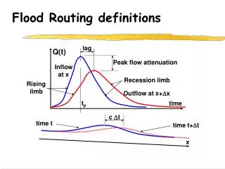
View Graphs - Graph of Inflow and Outflow Hydrographs“exit black X upper right corner”