Download
1 / 16
170 likes | 207 Views
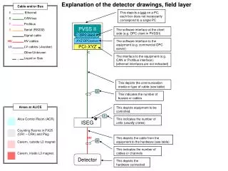
Explore the various Ethernet media types, such as coax, twisted pair, fiber optic, and wireless, along with access methods like CSMA/CD. Learn about Ethernet frames, MAC addresses, digital encoding, and segments.

E N D
Ethernet Oakton Community College CIS 238
Ethernet • Developed as Xerox Network System (XNS) by PARC • Original form is “DIX”, later Ethernet II • Standardized by IEEE as 802.2, 802.3 (wired), 802.11 (wireless) • 802.4 (Token Ring), 802.5 (Token Bus) no longer used
Media Types • Thicknet Coax (10 Base 5): several kilometers • Thinnet Coax (10 Base): thousands of meters • Unshielded twister pair: (10/100BaseT/1000BaseTX) – 100 M. 10GBaseT – 15M (CX) – 100M (10GBaseT) • Shielded twisted pair. Same a UTP. • Fiber Optic – multi-mode: 220-550M (50-62.5 micron), single mode: 10-70KM. • Wireless – B/G (2.4GHZ) < 100M, A (5GHZ) << 100M
Media Types • Coax almost never used, except maybe by the cable company. Replaced by fiber optic which uses less power, less susceptible to interference, same distance advantages at higher speeds. • Twisted pair is an “unbalanced” electrical circuit - no absolute ground like coax, so attenuation leads to severe distance limitations (100M). • “Twisted” to minimize electrical crosstalk caused by (counter) EMF. “Shielded” if external EMF is a factor. • Multiple fiber optic type from 10BaseFX to 100GBaseER4. Too many standards to list.
Media Access Control Address • 6 byte field burned into the Ethernet chip • Can be overridden as “local” address • Has meaning only on local network (OSI Layer 2) • Represented as 12 hexadecimal digits. • The first 3 bytes (6 hex numbers) represent the manufacturer (OUI) as assigned by IEEE.
Digital Encoding • Coax Manchester encoding: encoding a logic 0 is indicated by a 0 to 1 transition at the centre of the bit and a logic 1 is indicated by a 1 to 0 transition at the centre of the bit. This is used on coax media. Original Data: Value Sent - Logic 0: 0 to 1 (upward transition at bit centre) - Logic 1: 1 to 0 (downward transition at bit centre) • Example: data (1,1,0,1,0,0) being sent: • Shielded twisted pair uses transmission using a 4b/5b MLT code with three signal levels (as opposed to just two above). So 100 MBS uses 33 MHZ over 2 pair. Gigabit Ethernet utilizes five levels and 8b/10b encoding, sending 1 Gbps within 100 MHz of bandwidth over 4 pair..
Segments • Base Ethernet is a broadcast medium, every computer on a network section (segment) shares the same wire(s)/electrical connection. • Multiple sections can be connected together by digital “repeaters” to extend the range of a segment by repeating digital signals from one side to the other. This is an OSI layer 1 device. • Repeaters are passive devices (no MAC Address) but are always powered to repeat digital signals. • Coax Ethernet repeaters are subject to the 5/4/3 rule – 5 segments connected by 4 repeaters with three segments active - a limit of 30 active workstations. • A multi-port repeater is referred to as a “hub”. Usually only used with twisted pair wiring. • Hubs have their own version of the repeater rule when daisy-chained called the Class I (10 MBS, 4 hubs) or Class II (100 MBS 2 hubs) that define how they can be connected within a collision domain.
Access Method • Ethernet is a “broadcast” on each “segment” where multiple host(s) try to gain control of a single media. • Access is gained by sending a “sense” packet 64 bytes long on each segment (511 “bit times”). • Signal propagation times and attenuation determine the distance limit for each media type. • If another host transmits at the same time a “collision” is detected in a “jam” packet. • Each workstation then backs off a pseudo-random amount of time before re-trying. • This process is referred to a Collision Sense, Multiple Access with Collision Detection – CSMA/CD
LAN Segment – Collision Domain • The area within which CSMA/CD takes place is called a “collision domain”. With multiple workstations accessing the medium in this way, queueing theory states full utilization with this half-duplex protocol is 33%. • To connect two collision domain segments, a “bridge” is used connecting a collision domain segment to a port. This is an OSI Layer 2 device. • A bridge functions by listen, learn, forward. Separate CSMA/CD on each port - populating an internal MAC Address table assigning each MAC address to a port it responds on. • A multi-port bridge is called a switch. • Since each port on a switch terminates a collision domain; if only one device is connected to the port, CSMA/CD can be dropped. This allows the port to function in full-duplex (simultaneous send/receive) mode. • Simple switches only function as one Layer 2 LAN segment. Configurable switches can separate ports into logical semgment known as V(virtual)LANs. • Finally, a Layer 2 segment is terminated by a OSI Layer 3 device – a router.
Ethernet Frames • All information placed into Ethernet “packets” or frames. Multiple frame types: Ethernet II/DIX, 802.3, 802.2, 802.2 inside 802.3, 802.2 + Ethernet II or SNAP - used by multiple LAN protocols. • Ethernet frames preceded by an 8 byte “preamble” of 7 bytes alternating 1 and 0 for timing and one “flag” byte ending in 0x7e. • Ethernet packet has a header with Destination (MAC) Address, Source MAC Address and 2-byte Ethertype/Length field and terminated by a 32 bit Frame Check Sequence (FCS) representing a “hash” of the packet contents – excluding preamble. • 1500 Byte frame (data) limit. • A common network problem used to be Ethernet attached devices on the same LAN not “seeing” each other due use of different frame type (Netware IPX). As TCP/IP becomes the de-facto LAN protocol, these type of connectivity issues become rare since TCP/IP uses DIX/EII frame type by default. Though this is configurable on most NICs (but don’t do it). • If the EtherType/Length value is greater than 0x05DC (decimal 1500), then the frame is interpreted / processed as an Ethernet II packet.
Ethernet Frame Types • “Raw” Ethernet (Xerox format) • -------------------- Data direction • Type field values include: • 0x0600 XNS (Xerox)0x0800 IP (Internet protocol)0x6003 DECNET 0x8137 IPX
Ethernet Frame Types • IEEE Standard • ----------------------- Data direction
Ethernet Frame Types • 802.2 (protocol encapsulation header after 802.3 header) • ----------------------- Data direction • Used primarily for non-routed LAN protocols: 0x0404 SNA 0xF0F0 NETBEUI 0x0A0A for LLC2
Ethernet Frame Types • SNAP • ----------------------- Data direction • 802.2 header for DIX frame type • Primarily used for TCP/IP, IPX
802.11 Specification • 802.11b (channels 1-11 or 14) - Speeds of 5.5 or 11 Mb/sec - 2.4 GHZ spread spectrum - 100M inside, 300M outside • 802.11g (channels 1-11 or 14) - Speeds of 6-54 Mb/sec - 2.4 GHZ spread spectrum or QAM - 100M • 802.11n (MIMO) (channels 1-11 or 14) - Speeds to 150 Mb/sec - 2.4 GHZ QAM or other method - 100M, Full Duplex • 802.11a (23 channels, channel numbering varies) - Speeds of 6-54 Mb/sec - 5 GHz band - 100M Distance inside or outside • Coming soon: 802.11ac - full duplex gigabit wireless
Wireless Security • WEP (Wireless Enryption Protocol): - 64-bit key (40-bit secret code, 24-bit “init” vector) - 104 bit key (13 byte key as 26 hex digits) - symmetric key with CRC -32 check • WPA (WiFi Protected Access): - 3DES, 128 bit key, per packet, TKIP - seed “key phrase” 8-63 bytes • WPA2 (WiFi Protected Access 2): - AES, 256 bit key, per packet, CCMP - seed “key phrase” 8-63 byte • EAP (Extensible Authentication Protocol) for user based authentication in combination with 802.1X – port/mac security. - EAP types: EAP-TLS, EAP-TTLS/MSCHAPv2, PEAPv0/EAP-MSCHAPv2, PEAPv1/EAP-GTC, PEAP-TLS, EAP-SIM, EAP-AKA, EAP-FAST • Wireless frame types use double Ethernet headers to allow “hopping” from wireless access point to access point.