Download

1 / 15
150 likes | 163 Views
Learn how the Turnover Prevention Device (TPD) works with the Crane Management Unit (CMU) and its practical use. Understand the components and function of the TPD to prevent overturning accidents.

E N D
The Turnover Prevention Device Lifting With Your SPYDERCRANE KBT 5.3
Topic Overview and Contents This Topic (The Turnover Prevention Device) is designed to provide you with an understanding of how the Turnover Prevention Device (TPD) works You will learn about: • The various components that comprise the TPD • How the TPD Works • How the TPD works with the Crane Management Unit (CMU) • Practical Use It is YOUR RESPONSIBILITY to read and understand the user manuals included with your SPYDERCRANE and the warning decals posted on it This Topic covers the 095- and 200-Series SPYDERCRANE
Learning Objective(s) The learning objectives for this Lesson Topic are for each student to… • DLO 5.3.1: Explain the function and purpose of the TURNOVER PREVENTION DEVICE. • DLO 5.3.2: Describe the various components of the TURNOVER PREVENTION DEVICE. • DLO 5.3.3: Describe, generally, how the TURNOVER PREVENTION DEVICE works. • DLO 5.3.4: Explain the relationship between the TURNOVER PREVENTION DEVICE and the CRANE MANAGEMENT UNIT. • DLO 5.3.5: Describe the two ALERT CONDITIONS for the TURNOVER PREVENTION DEVICE. • DLO 5.3.6: Explain what you should do when alerted by the TURNOVER PREVENTION DEVICE.
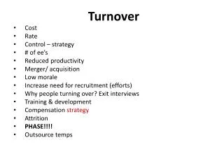
What the Turnover Prevention Device Does Acts as an OVERTURN PROTECTION SYSTEM Serves the same purpose as the conventional Load Moment Indicator (LMI) system Measures the SPYDERCRANE’s stability in real-time Generates TPD WARNING alarm when attached load is equal to 80% of the SPYDERCRANE’s load moment Generates TPD LOCKOUT alarm when attached load is equal to 90% of the SPYDERCRANE’s load moment • Also disconnects BOOM OUT, BOOM DOWN, SLEW, and HOIST commands
TPD Components The TPD is composed of two major components: The TPD LOAD CELL (x4) Detects and measures pressure at each outrigger Load Sensors (x4) Installed in the Upper Outrigger TPD Amplifier The TPD AMPLIFIER Gathers the pressure data from each Load Cell and compares them URW295CP1URS Determines stability status of the SPYDERCRANE based on the differences in pressure between OUTRIGGER PAIRS Communicates with the CMU to provide stability alarms and function kick-out (FKOs)
TPD Amplifier Status Panel Receives Load Cell data and compares Indicates Load Cell status with orange lights Channels A-D correspond with Outriggers #1-4 URW295CP1URS
TPD and The Turnover Point The weight of the SPYDERCRANE’s carrier of generates Load Moment at the four outrigger contact points The load suspended from the SPYDERCRANE’s hook also generates Load Moment As the Load’s Load Moment increases, the pressure at the outrigger contact points between the SPYDERCRANE and the load also increases As the ground pressure at the outriggers between the SPYDERCRANE and the load increases, the ground pressure at the outriggers on the opposite side of the SPYDERCRANE decreases When the load moment generated by the load is greater than the load moment generated by the SPYDERCRANE, the Turnover Point is reached and the SPYDERCRANE will overturn
TPD Load Cell Pairs The TPD measures the ground pressure for PAIRS of ADJACENT Load Cells 2 3 i.e., Outriggers 1+2, 2+3, 3+4, 4+1 The TPD only measures the light-side outriggers Once the ground pressure at the light-side falls to 20% of the SPYDERCRANE’s load moment (80% turnover), it generates a TPD Warning 1 4 Once the ground pressure at the light-side falls to 10% of the SPYDERCRANE’s load moment (90% turnover), it generates a TPD Lockout
When the loaded boom is over Outrigger #3, its Load Cell is registering increasing pressure (“getting heavy”) Outrigger #1 is registering decreasing pressure (“getting light”); Outriggers #2 and #4 are neutral 2 3 TPD Amplifier registers that only ONE Load Cell is getting light and ignores it; three outriggers are still stabilizing the SPYDERCRANE 1 4 As the boom is slewed towards Outrigger #4, it begins getting heavy Outriggers #1 and #2 begin getting light
Working radius is being increased; moving the load further from the deployed SPYDERCRANE Outriggers #3 and #4 are getting heavy as the load’s Load Moment increases SPYDERCRANE is beginning to tip as load begins pulling Outriggers #1 and #2 off the ground TMP Amplifier provides a Warning Alarm when the SPYDERCRANE is at 80% of turnover TMP Amplifier provides a Lockout Alarm when the SPYDERCRANE is at 90% of turnover At 90%, CMU commands a function kick-out for BOOM DOWN, BOOM SLEW, BOOM OUT, and HOIST
How the TPD Works: Visual TS-100 RUN TPD Warning ERR ch. D Code Indicator “Nearing Turnover Threshold” ch. C 16 ch. B ch. A ZERO RESET
How the TPD Works: Visual TS-100 RUN TPD Lockout ERR ch. D Code Indicator “Turnover Threshold Reached” ch. C 15 ch. B ch. A ZERO RESET
The TPD in a Nutshell The TPD is a PASSIVE Operator Aid: it only requires operator intervention as an exception • The TPD is constantly monitoring the pressure conditions at each outrigger • The TPD alerts the operator when the ground pressure values of two ADJACENT outriggers falls within 80% of the stability limit of the deployed SPYDERCRANE • The TPD will signal the CMU to FKO BOOM DOWN, BOOM OUT, HOIST, and SLEW when the pressure values are within 90% of the stability limit of the deployed SPYDERCRANE • The PRIMARY alerting mechanism is audible; you will hear the TPD Buzzer signal Warning (intermittent) and Lockout (solid tone) • The TPD Amplifier is also used to monitor/diagnose the TPD System • The CMU Code Indicator is a SECONDARY alerting mechanism
The TPD in Practical Lifting Operations To use the TPD, just conduct your normal lifting operations • Make all boom movements slow and deliberate • Avoid sudden starts and stops • When the TPD WARNING sounds, consider where the load is in relation to the SPYDERCRANE and consider whether you can continue (will the working radius increase much more?) or recover (can I reduce the working radius and still finish the lift?) • If the TPD LOCKOUT sounds, you MUST begin load recovery: you can only BOOM UP, BOOM IN, and WINCH DOWN • If the SPYDERCRANE FKOs and the TPD Buzzer DOES NOT sound, check the CMU Code Indicator for Code 15 (Lockout) and check the TPD Buzzer Mute to make sure it is turned ON
Learning Objective(s) The desired learning objectives for this Segment Topic is for each student to… • Explain the function and purpose of the TURNOVER PREVENTION DEVICE • Describe the various components of the TURNOVER PREVENTION DEVICE • Describe, generally, how the TURNOVER PREVENTION DEVICE works • Explain the relationship between the TURNOVER PREVENTION DEVICE and the CRANE MANAGEMENT UNIT • Explain the TWOALARM CONDITIONS for the TURNOVER PREVENTION DEVICE • Explain the TWOALERT ACTIONS related to the TURNOVER PREVENTION DEVICE ALARM CONDITIONS