Download
1 / 27
270 likes | 303 Views
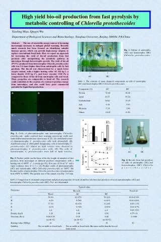
This study explores the impact of radiation damage on MOS structures, focusing on MOS-Capacitance and DEPFET technology. It covers damage mechanisms, experimental conditions, and results, emphasizing the importance of radiation hardness in research. The research delves into the intricate interactions of ionizing radiation with electronic structures, defects generation, interface traps, and long-term effects on devices. Conclusions highlight the significance of understanding and mitigating radiation-induced damage to ensure the reliability and performance of semiconductor devices in high-energy physics experiments.

E N D
Radiation Damage on MOS-Structure Q. Wei, L. Andricek, H-G. Moser, R. H. Richter Max-Planck-Institute for Physics Semiconductor Laboratory RD50, Vilnius, 2007 Qingyu Wei, MPI für Physik, HLL
Outline • Motivation • Radiation damage & effects on MOS-structure • Experimental Conditions and Results • Conclusion
Motivation Physics topics • Unexpected phenomena • Mechanism of electroweak symmetry breaking • New physics: SUSY; extra dimension; link to cosmology International Linear Collider precise vertex detector (DEPFET) Depleted P-channel FET To do Radiation on MOS-structure (MOS-Capacitance & -DEPFET ) Research of radiation effect (damage mechanism & model) Radiation hardness structure TESLA TDR Design
MOS-Structure Ionization in SiO2 Interaction with electronic structure of atoms by photoelectric, Compton & pair-production Carrier injection from contacts e-h pair creation in SiO2 Bond breaking e-h transport in SiO2 Defect generation Release of mobile Impurities (H, OH, Na, etc.) Hole trapping + Electron capture Defect migration in strained region Migration of impurities Oxide charge Interface trap Accumulated TID reach its tolerance limits Device degradation or failure Radiation Damage I
Radiation Damage II • Radiation damage in MOS-Structure: • Surface damage due to Ionizing Energy Loss (IEL) • accumulation of charge in the oxide (SiO2) and Si/SiO2 interface • Oxide charge shifts of flat band voltage, (depleted enhancement) annealing at RT • Interface traps leakage current, degradation of transconduction,… no annealing below 400 0C • S/N Ratio deteriorated!
Radiation induced Interface trap Si 1.12ev SiO2 Gate Long-term Hole trapping near Si/SiO2 Interface Hopping Transport of Holes through localized states in SiO2 Bulk Electron/Hole Pairs Generated by ionizing radiation Si Si Electric active Interface state Damage mechanism (MOS) I Ionizing radiation (positive oxide charge) Damage mechanisms: interface state Shifts of flat band voltage: ~ Nox Stretch-out of CV curve: ~ Nit Nox: positive oxide charge and positively charged oxide traps have to be compensated by a more negative gate voltage negative shift of the threshold voltage (~tox2) Nit: increased density of interface traps higher 1/f noise and reduced mobility (gm)
equilibrium Saturation Begin Recombination Recombination Rejection Trapp filling SiO2 Si Damage mechanism (MOS) II Saturation mechanism • Reservoir: hole traps are not exhausted, unless a larger bias voltage is applied on the gate! • Saturation: equilibrium between trapped filling and recombination • Generated holes are pushed away! • Recombination of trapped holes with electrons - Recombination of tunneled electrons from silicon into interface with trapped holes!
Experiment Conditions and Methods • Irradiation (X-Ray): • Co60 (1.17 MeV and 1.33 MeV) • GSF – National Research Center for Environment and Health, Munich • CaliFa (17.44 KeV) • Max-Planck-Institute Semiconductor Labor, Munich • Roentgen facility (20 KeV) • Research center, Karlsruhe • Dose: irradiation up to 1 Mrad with different dose rate (1rad=0.01J/kg) • Process: No annealing during irradiation ~ irradiation duration from 1 day to 1 week • Radiation levels at the ILC VTX: Dionization≈ 100 .. 200 Krad ≈ 1010 .. 1011 neq(1MeV )/cm2 • Comparison of different semiconductor devices
"ON" "OFF" Results for MOSDEPFET Bias during irradiaton: 1: empty int. gate, in „off“ state, VGS= 5V, VDrain=-5V Eox ≈ 0 2: empty int. gate, in „on“ state, VGS=-5V, VDrain=-5V Eox ≈ -250kV/cm
s=85mV/dec Vth=-0.2V s=155mV/dec Vth=-4.5V Transconductance and Subtreshold slope No change in the transconductance gm 300 krad Nit≈2·1011 cm-2 912 krad Nit≈7·1011 cm-2 Literature: After 1Mrad 200 nm (SiO2): Nit ≈ 1013 cm-2
Results for MOS-C Flat band voltage Shift Nox HF/LF CV Nit
VG + 0 - SiO2 Si For MOS-C Bias Effect DEPFET thickness dependence dn
Radiation hardness by Nitride-layer (MNOS) For MOS-C Vg=+10V Vg=+5V Vg=-10V Vg=-5V
Vg < 0 Me Nitride Oxide Si Jn J0 EFM Qni Vg Qox EC EF h: e: Damage mechanism (MNOS) I Energy band diagram of MNOS structure Vg > 0 Me Nitride Oxide Si EC J0 Jn EF Qox Vg Qni EFM Mobility of electron is faster than hole in SiO2, and reversely in Nitride Discontinuity of current density Jn-J0 in short time lead to charge carriers accumulation & trapping in N/O strained interface field dependence of current density & thickness of the dielectrics plays an important role! charge in Si/SiO interface donot affect the field distribution in dielectrics!
Damage mechanism II + 0 - VG Nitride Trapp source for e & p SiO2 Si Recombination
Annealing for surface damage Oxide charge decrease with time: (Tunnel annealing @ RT)
Conclusion • Radiation experiment • Study of saturation effect for surface damage (equilibrium between generation and recombination) • Study of bias dependence(“+“,“0“,“-“) • Study of different semiconductor devices, which are with different oxide thickness - to see the kind of relation between Vfb and oxide thickness (doxn ) • Radiation hardness • Reduced oxide thickness improves radiation hardness • Additional Nitride layer serve as a good protection against ionizing radiation (electron trapping!) • Surface damage can be reduced through annealing process with time
Results for gated diode Shifts of generated current: Increase of maximal current: Increase of surface generation velocity & decrease of lifetime due to radiation:
Chip thickness (nm) Electrically measured equivalent oxide thickness (CV) Pre-Rad VFB(V) Post-Rad VFB(V) ~1Mrad Vg=-10V Post-Rad VFB(V) ~1Mrad Vg=-5V Post-Rad VFB(V) ~1Mrad Vg=0V Post-Rad VFB(V) ~1Mrad Vg=+5V Post-Rad VFB(V) ~1Mrad Vg=+10V Equivalent Oxide thickness Oxide/Nitride thickness 86 76 -0,6 6 5,3 4,1 18,6 19 86 22,7 91 86/10 85 -1,4 4,4 3,3 2,3 16,4 -0,7 7,1 6 16,6 29,4 100 100 95 5,5 105 100/10 -1.4 103 5 3,4 2,6 21,3 31,5 Mathematics Expression I
Mathematics Expression III • Assumption (positive gate bias) • Recombination at interface (Si/SiO or N/O) should be neglected • Electron or hole trapps are distributed approximately homogen at interface • There are no trapped charge at interface (pre-Rad)
Erde V V Al/PolyGate A Al Edge Substrate P+ N Poly-gate Al-gate Al Al P+ P+ grounding Edge MOS-Gated Diode (device profile)
Low dose rate High dose rate SiO2 Si Dose rate effect
Radiation Damage • Two types of radiation damage in MOS-Structure: • Surface damage due to Ionizing Energy Loss (IEL) • accumulation of charge in the oxide (SiO2) and Si/SiO2 interface • Oxide charge shifts of flat band voltage, (depleted enhancement) • Interface traps leakage current, degradation of transconduction,… • Bulk damage due to Non Ionizing Energy Loss (NIEL) • displacement damage, built up of crystal defects • Increase of leakage current increase of shot noise,… • Change of effective doping concentration higher depletion voltage,… • Increase of charge carrier trapping signal loss! • S/N Ratio deteriorated!
80 min 60C Annealing For surface damage: Oxide charge decrease with time: (Tunnel annealing @ RT) For bulk damage: Leakage current decrease with time: “Beneficial annealing” & “Reverse annealing”