Download
1 / 68
680 likes | 902 Views
From Global Illumination To Inverse Global Illumination. Yizhou Yu Computer Science Division University of California at Berkeley. Publications. http://www.cs.berkeley.edu/~yyz.

E N D
From Global IlluminationTo Inverse Global Illumination Yizhou Yu Computer Science Division University of California at Berkeley
Publications http://www.cs.berkeley.edu/~yyz • Y. Yu and H. Wu, A Rendering Equation for Specular Transfers and Its Integration into Global Illumination, Eurographics’97 • P. Debevec, Y. Yu and G. Borshukov, Efficient View-Dependent Image-Based Rendering with Projective Texture-Mapping, Eurographics Workshop on Rendering’98 • Y. Yu and J. Malik, Recovering Photometric Properties of Architectural Scenes from Photographs, Siggraph’98 • Y. Yu, P. Debevec, J. Malik and T. Hawkins, Inverse Global Illumination: Recovering Reflectance Models of Real Scenes from Photographs, Siggraph’99
Computer Graphics & Vision • Graphics • Solving forward simulation • Synthesizing images from geometry and reflectance • Vision • Recovering geometry and reflectance • Extracting data from images vision graphics Images Geometry & Reflectance Images
Global Illumination Reflectance Properties Light Transport Radiance Maps Geometry Light Sources
Reflectance Properties Bidirectional Reflectance Distribution Function(BRDF) (wavelength dependent) Specular Incident light Diffuse
Geometry • A polygonal mesh and/or a set of curved surface patches
Light Sources • 3D positions and directional radiance distributions
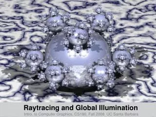
Light Transport The Rendering Equation [ Kajiya’86 ]
Example of Rendering Using Global Illumination With a mirror Without the mirror Yu & Wu [ Eurographics’97 ] use bi-directional wavefront tracing to calculate illumination from area sources via curved ideal specular reflectors.
The Problem • The physics of light transport has been well understood. • In the absence of real-world geometry and reflectance, rendered images still look synthetic. • Solution: Image-based Modeling and Rendering (IBMR)
Image-based Modeling and Rendering • 1st Generation----vary viewpoint but not lighting • Recover geometry ( explicit or implicit ) • Acquire texture maps • Facade, Virtualized Reality, View Morphing, Plenoptic Modeling etc.
A Synthetic Sunrise Sequence 5:00am 5:30am 6:00am 6:30am 7:00am 8:00am 9:00am 10:00am One Day at the End of March
The Problem • Texture Maps arenot Reflectance Maps ! • Need to factorize images into lighting and reflectance maps Illumination Radiance Reflectance
Image-based Modeling and Rendering • 2nd Generation----vary viewpoint and lighting • Recover geometry • Recover reflectance maps • Permits rendering using physically based light transport methods
Outline of the Rest of the Talk • 1st Generation IBMR • Real-Time View-Dependent Projective Texture-Mapping • 2nd Generation IBMR • General Problem: closely positioned multiple objects • Simplified Situation: Isolated Objects
Outline • 1st Generation IBMR • Real-Time View-Dependent Projective Texture-Mapping • 2nd Generation IBMR • General Problem: closely positioned multiple objects • Simplified Situation: Isolated Objects
Real-Time View-Dependent Texture Mapping • VDTM was originally from Façade [ Debevec, Taylor & Malik, Siggraph’96]. • Software implementation • 10 seconds per frame • Real-Time VDTM • Software object-space visibility preprocessing + hardware projective texture-mapping • 20 frames per second on SGI RealityEngine • 60 frames per second on SGI Onyx2 InfiniteReality
Motivation for Visibility Processing: Artifacts Caused by Hardware Camera Image Geometry
Visibility Processing Results The tower The rest of the campus
Outline • 1st Generation IBMR • Real-Time View-Dependent Projective Texture-Mapping • 2nd Generation IBMR • General Problem: closely positioned multiple objects • Simplified Situation: Isolated Objects
Previous Work • BRDF Measurement in the Laboratory • [ Ward 92 ], [Dana, Ginneken, Nayar & Koenderink 97] • Isolated Objects under Direct Illumination • [ Sato, Wheeler & Ikeuchi 97 ] General case of multiple objects under mutual illumination has not been studied.
Image-based Reflectance Recovery • Start from photographs • Recover geometric model • Measure and/or recover illumination • Recover parametric models for reflectance • Design or Predict Novel illumination • Re-render the scene
Global Illumination Reflectance Properties Radiance Maps Geometry Light Sources
Inverse Global Illumination Reflectance Properties Radiance Maps Geometry Light Sources
Synthesized Images of the Room under Original and Novel Lighting
IGI Outline • IGI for Lambertian surfaces • IGI for isolated specular surface • IGI for general surfaces • Computing diffuse albedo maps • Results
Inverse Radiosity with Lambertian Surfaces Aj LPiAj Pi • Bi, Bj, Ei measured using HDR photographs • Fij known because geometry is known • Solve for diffuse albedo LCkAj LCvPi Ck Cv
Recovering Specular Properties from Direct Illumination • Specular Kernel Ki as in [ Ward 92 ] N H
Parametric BRDF Model [ Ward 92 ] N H Isotropic Kernel Anisotropic Kernel
Recovering Diffuse and Specular Reflectance under Mutual Illumination • Specular component of LPiAj is not known. ( unlike diffuse case, where LPiAj = LCkAj ) Aj LPiAj LCkAj Pi LCvPi Ck Cv
Solution: iteratively estimate specular component. • Initialize • Repeat • Estimate BRDF parameters for each surface • Update and
Estimation of S • Estimate specular component of by ray-tracing using current guess of reflectance parameters. • Similarly for • Difference gives S • Currently we use one-bounce approximation, but could be generalized. Aj LPiAj LPiAj Pi LCkAj LCkAj Ck LCvPi Cv
Inverse Global Illumination • Detect specular highlight blobs on the surfaces. • Choose a set of sample points inside and around each highlight area. • Build hierarchical links between sample points and facets in the environment and use ray tracing to detect occlusion. • Assign to each facet one photograph and one average radiance value captured at the camera position. • Assign zero to Delta_S at each hierarchical link. • For iter = 1 to n • For each hierarchical link, use its Delta_S to update its radiance value. • For each surface having highlight areas, optimize its BRDF parameters. • For each hierarchical link, estimate its Delta_S with the new BRDF parameters. • End
Recovering Diffuse Albedo Maps • Estimate specular component at each pixel from the recovered BRDF parameters using Monte Carlo ray-tracing. • Subtract specular component to get the diffuse component of radiance, Ld(x). • Gather irradiance, Ir(x), using Form-Factors over each surface. • Combine from multiple photographs by robust weighted average.
Results for a Simulated Cubical Room: I Diffuse Albedo
Results for a Simulated Cubical Room: II Specular Roughness
Diffuse Albedo Maps of Identical Posters in Different Parts of the Room
Inverting Color Bleed Input Photograph Output Albedo Map
Contributions • A digital camera is the only data acquisition equipment used. • Adopt an iterative procedure to obtain radiance distributions from specular surfaces. • Exploit spatial coherence to recover specular reflectance models from one single photograph. • Make use of multiple photographs to recover high-resolution diffuse albedo maps.
Outline • 1st Generation IBMR • Real-Time View-Dependent Projective Texture-Mapping • 2nd Generation IBMR • General Problem: closely positioned multiple objects • Simplified Situation: Isolated Objects