Download
1 / 21
210 likes | 358 Views
Flow and Congestion Control. Ram Dantu (compiled from various text books). receive side of TCP connection has a receive buffer:. speed-matching service: matching the send rate to the receiving app’s drain rate. flow control. sender won’t overflow receiver’s buffer by transmitting too much,

E N D
Flow and Congestion Control Ram Dantu (compiled from various text books) Transport Layer
receive side of TCP connection has a receive buffer: speed-matching service: matching the send rate to the receiving app’s drain rate flow control sender won’t overflow receiver’s buffer by transmitting too much, too fast TCP Flow Control • app process may be slow at reading from buffer Transport Layer
(Suppose TCP receiver discards out-of-order segments) spare room in buffer = RcvWindow = RcvBuffer-[LastByteRcvd - LastByteRead] Rcvr advertises spare room by including value of RcvWindow in segments Sender limits unACKed data to RcvWindow guarantees receive buffer doesn’t overflow TCP Flow control: how it works Transport Layer
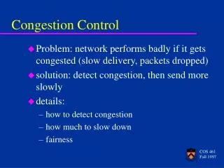
Congestion: informally: “too many sources sending too much data too fast for network to handle” different from flow control! manifestations: lost packets (buffer overflow at routers) long delays (queueing in router buffers) a top-10 problem! Principles of Congestion Control Transport Layer
Congestion: A Close-up View packet loss knee cliff • knee – point after which • throughput increases very slowly • delay increases fast • cliff – point after which • throughput starts to decrease very fast to zero (congestion collapse) • delay approaches infinity • Note (in an M/M/1 queue) • delay = 1/(1 – utilization) Throughput congestion collapse Load Delay Load Transport Layer
Congestion Control vs. Congestion Avoidance • Congestion control goal • stay left of cliff • Congestion avoidance goal • stay left of knee • Right of cliff: • Congestion collapse knee cliff Throughput congestion collapse Load Transport Layer
Congestion Collapse: How Bad is It? • Definition: Increase in network load results in decrease of useful work done • Many possible causes • Spurious retransmissions of packets still in flight • Undelivered packets • Packets consume resources and are dropped elsewhere in network • Fragments • Mismatch of transmission and retransmission units • Control traffic • Large percentage of traffic is for control • Stale or unwanted packets • Packets that are delayed on long queues Transport Layer
Solution Directions…. i i • Problem: demand outstrips available capacity 1 Demand Capacity n • If information about i , and is known in a central location where control of i or can be effected with zero time delays, the congestion problem is solved! • Capacity () cannot be provisioned very fast => demand must be managed • Perfect callback: Admit packets into the network from the user only when the network has capacity (bandwidth and buffers) to get the packet across. Transport Layer
four senders multihop paths timeout/retransmit l l in in Host A Host B Causes/costs of congestion: scenario 3 Q:what happens as and increase ? lout lin : original data l'in : original data, plus retransmitted data finite shared output link buffers Transport Layer
Host A Host B Causes/costs of congestion: scenario 3 lout Another “cost” of congestion: • when packet dropped, any “upstream transmission capacity used for that packet was wasted! Transport Layer
End-end congestion control: no explicit feedback from network congestion inferred from end-system observed loss, delay approach taken by TCP Network-assisted congestion control: routers provide feedback to end systems single bit indicating congestion (SNA, DECbit, TCP/IP ECN, ATM) explicit rate sender should send at Approaches towards congestion control Two broad approaches towards congestion control: Transport Layer
end-end control (no network assistance) sender limits transmission: LastByteSent-LastByteAcked CongWin Roughly, CongWin is dynamic, function of perceived network congestion How does sender perceive congestion? loss event = timeout or 3 duplicate acks TCP sender reduces rate (CongWin) after loss event three mechanisms: AIMD slow start conservative after timeout events CongWin rate = Bytes/sec RTT TCP Congestion Control Transport Layer
multiplicative decrease: cut CongWin in half after loss event TCP AIMD (Additive increase and multiplicative decrease) additive increase: increase CongWin by 1 MSS every RTT in the absence of loss events: probing Long-lived TCP connection Transport Layer
When connection begins, CongWin = 1 MSS Example: MSS = 500 bytes & RTT = 200 msec initial rate = 20 kbps available bandwidth may be >> MSS/RTT desirable to quickly ramp up to respectable rate TCP Slow Start • When connection begins, increase rate exponentially fast until first loss event Transport Layer
When connection begins, increase rate exponentially until first loss event: double CongWin every RTT done by incrementing CongWin for every ACK received Summary: initial rate is slow but ramps up exponentially fast Host A Host B one segment RTT two segments four segments time TCP Slow Start (more) Transport Layer
After 3 dup ACKs: CongWin is cut in half window then grows linearly But after timeout event: CongWin instead set to 1 MSS; window then grows exponentially to a threshold, then grows linearly Refinement Philosophy: • 3 dup ACKs indicates network capable of delivering some segments • timeout before 3 dup ACKs is “more alarming” Transport Layer
Q: When should the exponential increase switch to linear? A: When CongWin gets to 1/2 of its value before timeout. Implementation: Variable Threshold At loss event, Threshold is set to 1/2 of CongWin just before loss event Refinement (more) Transport Layer
Summary: TCP Congestion Control • When CongWin is below Threshold, sender in slow-start phase, window grows exponentially. • When CongWin is above Threshold, sender is in congestion-avoidance phase, window grows linearly. • When a triple duplicate ACK occurs, Threshold set to CongWin/2 and CongWin set to Threshold. • When timeout occurs, Threshold set to CongWin/2 and CongWin is set to 1 MSS. Transport Layer
Fairness goal: if K TCP sessions share same bottleneck link of bandwidth R, each should have average rate of R/K TCP connection 1 bottleneck router capacity R TCP connection 2 TCP Fairness Transport Layer
Two competing sessions: Additive increase gives slope of 1, as throughout increases multiplicative decrease decreases throughput proportionally Why is TCP fair? equal bandwidth share R loss: decrease window by factor of 2 congestion avoidance: additive increase Connection 2 throughput loss: decrease window by factor of 2 congestion avoidance: additive increase Connection 1 throughput R Transport Layer
Fairness and UDP Multimedia apps often do not use TCP do not want rate throttled by congestion control Instead use UDP: pump audio/video at constant rate, tolerate packet loss Research area: TCP friendly Fairness and parallel TCP connections nothing prevents app from opening parallel connections between 2 hosts. Web browsers do this Example: link of rate R supporting 9 cnctions; new app asks for 1 TCP, gets rate R/10 new app asks for 11 TCPs, gets R/2 ! Fairness (more) Transport Layer