Download
1 / 82
1.3k likes | 2.62k Views
Analog and Digital Signals. NETE 0510 Dr.Apichan Kanjanavapastit. Analog and Digital. Analog refers to something that is continuous—a set of specific points of data and all possible points between

E N D
Analog and Digital Signals NETE 0510 Dr.Apichan Kanjanavapastit
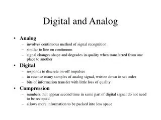
Analog and Digital • Analog refers to something that is continuous—a set of specific points of data and all possible points between • Digital refers to something that is discrete—a set of specific points of data with no other points in between
Analog and Digital Data • Data can be analog or digital • Human voice is an example of analog data. When somebody speaks, a continuous wave is created in the air. This can be captured by a microphone and converted to an analog signal
Analog and Digital Data (cont.) • An example of digital data is data stored in the memory of computer in the form of 0s and 1s • It is usually converted to a digital signal when it is transferred from one position to another inside or outside the computer
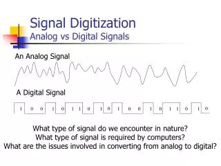
Analog and Digital Signals • An analog signal is a continuous wave form that changes smoothly over time • A digital signal is discrete. It can have only a limited number of defined values, often as simple as 1 and 0
Periodic Signals • A signal is a periodic signal if it completes a pattern within a measurable time frame, called period, and repeats that pattern over identical subsequent periods • The completion of one full pattern is called a cycle • A period is defined as the amount of time (in seconds) required to complete one cycle
Aperiodic Signals • An aperiodic, or nonperiodic, signal changes constantly without exhibiting a pattern or cycle that repeats over time • It has been proved by a Fourier transform that any aperiodic signal can be decomposed into an infinite number of periodic signals
Analog Signals • Analog signals can be classified as simple or composite • A simple analog signal, or a sine wave, cannot be decomposed into simpler signals • A composite analog signal is composed of multiple sine wave Simple analog signal Composite analog signal
Simple Analog Signals • The sine wave is the most fundamental form of a periodic analog signal • Visualized as a simple oscillating curve, its change over the course of a cycle is smooth and consistent, a continuous, rolling flow • Sine waves can be fully described by 3 characteristics: amplitude, period or frequency, and phase
Amplitude • On a graph, the amplitude of a signal is the value of the signal at any point on the wave • Amplitude is measured in either volts, amperes, or watts, depending on the type of signal
Period or Frequency • Period refers to the amount of time, in second, a signal needs to complete one cycle • Frequency refers to the number of periods in one second; thus the frequency of a signal is its number of cycles per second
Example#1 • Show 20 MHz in Hz, kHz, and GHz
Example#2 • A sine wave has a frequency of 20 kHz. What is its period?
Phase • The term phase describes the position of the waveform relative to time zero; it indicates the status of the first cycle • Phase is measured in degrees or radians (360 degrees is 2*pi radians)
Phase Difference • Two oscillators that have the same frequency and different phases have a phase difference, and the oscillators are said to be out of phase with each • If the phase difference is 180 degrees (π radians), then the two oscillators are said to be in antiphase. If two interacting waves meet at a point where they are in antiphase, then destructive interference will occur • It is common for waves of electromagnetic (light, RF), acoustic (sound) or other energy to become superimposed in their transmission medium
Time and Frequency Domains • The time domain plot shows changes in signal amplitude with respect to time, phase and frequency are not explicitly measured on a time-domain plot • To show the relationship between amplitude and frequency, we can use what is called a frequency-domain plot
Composite Signals • Many useful wave forms do not change in a single smooth curve between a minimum and a maximum amplitude; they jump, slide, wobble, spike, and dip • In fact, it can be shown that any periodic signal can be decomposed into a collection of sine waves, each having a measurable amplitude, frequency, and phase • To decompose a composite signal into its components, Fourier analysis is needed
Frequency Spectrum and Bandwidth • The frequency spectrum of a signal is the collection of all the component frequencies it contains and is shown using a frequency-domain graph • The bandwidth of a signal is the width of the frequency spectrum • To calculate the bandwidth, subtract the lowest frequency from the highest frequency of the range
Digital Signals • Most digital signals are aperiodic and period or frequency is not appropriate • Bit interval (instead of period) and bit rate (instead of frequency) are used to describe digital signals • The bit interval is the time required to send one single bit. The bit rate is the number of bit intervals per second (bits per second: bps)
Example#3 • A digital signal has a bit interval of 125 microseconds. What is the bit rate
Transmission of Digital Signals • A digital signal can be decomposed into an infinite number of sine waves called harmonics, each with a different amplitude, frequency, and phase • When we send a digital signal along a transmission medium, some of the components are not passed through the medium, corruption of the signal at the receiver is the result
Transmission of Digital Signals through Low Pass Channel • Baseband transmission of a digital signal that preserves the shape of the digital signal is possible only if we have a low-pass Channel with an infinite or very wide bandwidth
Transmission of Digital Signals through Low Pass Channel (cont.) • In practice, it is impossible to have an infinite low pass channel. Most low pass channels are band-limited channels • In order to preserve the shape of the digital signals passing through a band-limited channel, a minimum bandwidth of the digital signals is required
Calculation of the Minimum Bandwidth • Approximate the digital signal with an analog signal • For a digital signal of bit rate N, to roughly simulate this signal, consider the worst case, a maximum number of changes in the digital signal, e.g., 010101… or 101010…. • We need an analog signal of frequency Minimum bandwidth = N/2
Example#4 • What is the maximum bit rate of the 150 kHz channel?
Transmission of Digital Signals through Band Pass Channel • Band-pass channel is a channel with a bandwidth that does not start from zero • To transmit a digital signal through band pass channel, the signal must be transform to a form of analog signal using modulation technique • This digital transmission technique is called broadband transmission
Encoding and Modulating • Data stored in a computer are in the form of 0s and 1s. To be carried from one place to another, data are usually converted to digital signals. This is called digital-to-digital conversion or encoding digital data into a digital signal • Sometimes, we need to convert an analog signal into a digital signal. This is called analog-to-digital conversion or digitizing an analog signal
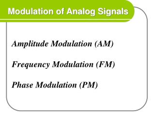
Encoding and Modulating (cont.) • At other times, we want to send a digital signal coming out of a computer through a medium designed for an analog signal. The signal produced by the computer should be converted to an analog signal. This is called digital-to-analog conversion or modulating a digital signal • Often an analog signal such as voice or music is sent over long distances using analog media. However, the frequency of the voice or music is not appropriate for this kind of transmission; the signal should be carried by a higher-frequency signal; This is called analog-to-analog conversion or modulating an analog signal
Encoding and Modulating (cont.) digital-to-digital conversion analog-to-digital conversion digital-to-analog conversion
Digital Line Coding (Digital-to-Digital Conversion) • Line coding is a process of converting digital data to digital signal • There are a number of line coding techniques but they fall into 3 broad categories: unipolar, polar, and bipolar
Unipolar • Unipolar encoding is very simple and very primitive. Unipolar is so named because it uses only one polarity • In unipolar Non-Return-to-Zero (NRZ), this polarity is assigned to one of the two binary states, usually the 1. The other state usually the 0 is represented by zero voltage
The Problems of Unipolar Encoding • Unipolar encoding has at least two problems that make it less desirable: a DC component and synchronization • DC Component. Since the average amplitude of a unipolar encoded signal is nonzero, this creates what is called a direct current (DC) component (a component with zero frequency) • When a signal contains a DC component, it cannot travel through media that cannot handle DC components causes a DC wander problem when transmitting a long string of 1s or 0s
The Problems of Unipolar Encoding (cont.) • When a signal is unvarying, the receiver cannot determine the beginning and ending of each bit • Therefore, a synchronization problem in unipolar encoding can occur whenever the data stream includes a long uninterrupted series of 1s or 0s • Lack of synchronization between the sender’s and the receiver’s clocks distorts the timing of the signal
Example#5 • In a digital transmission, the receiver clock is 0.1 percent faster than the sender clock. How many extra bits per second does the receiver receive if the data rate is 1 kbps?
Polar • Polar encoding uses 2 voltage level: one positive and one negative • By using both levels, the average voltage level on the line is reduced and the DC component problem of unipolar encoding is alleviated • The three most popular polar encodings are NRZ, return to zero (RZ), and biphase
Polar (cont.) • NRZ encoding includes two methods: NRZ level (NRZ-L), and NRZ-invert (NRZ-I) • Biphase also refers to 2 methods. The first, Manchester, is the method used by ethernet LANs. The second, Differential Manchester, is the method used by Token Ring LANs.
Nonreturn to Zero (NRZ) • NRZ-L. The level of the signal depends on the type of bit it represents • A positive voltage usually means the bit is a 0, and a negative voltage means the bit is a 1 (or vice versa); thus, the level of the signal is dependent upon the state of the bit • NRZ-I. An inversion of the voltage level represents a 1 bit. A 0 bit is represented by no change
Return to Zero (RZ) • As we see that the NRZ-I accomplishes the synchronization just only the 1 bits, to change every bit, we need more than just 2 values • In RZ, the signal changes not between bits but during each bit. And a positive voltage means 1 and a negative voltage means 0 • In addition, a 1 bit is actually represented by positive-to-zero and a0 bit by negative-to-zero
RZ (cont.) • The main disadvantage of RZ encoding is that it requires 2 signal changes to encode one bit and therefore occupies more bandwidth
Biphase • In biphase, the signal changes at the middle of the bit interval but does not return to zero. Instead, it continues to the opposite pole • There are 2 types of biphase encoding: Manchester and differential Manchester • In Manchester, a negative-to-positive transition represents binary 1 and a positive-to-negative transition represents binary 0
Biphase (cont.) • In Differential Manchester, the presence or absence of an additional transition at the beginning of the interval is used to identify the bit • A transition means binary 0 and no transition means binary 1; thus differential Manchester requires 2 signal changes to represent binary 0 but only one to represent binary 1
Bipolar • Bipolar encoding uses 3 voltage levels: positive, negative, and zero • The 1s are represented by alternating positive and negative voltages • The zero level is used to represent binary 0 • Three types of bipolar encoding are in popular used by the data communications industry: AMI, B8ZS and HDB3
Alternate Mark Inversion (AMI) • AMI means alternate 1 inversion. A zero voltage represents binary 0 • A variation of AMI is called pseudoternary, in which binary 0 alternates between positive and negative voltages • Two variations of AMI have been developed to solve the problem of synchronizing sequential 0s: bipolar 8-zero substitution (B8ZS) and high-density bipolar 3 (HDB3)
High-Density Bipolar 3 (HDB3) • HDB3 introduces changes into the bipolar AMI pattern every time 4 consecutive 0s are encountered • HDB3 is based on the polarity of the previous 1 bit. It also looks at the number of 1s that have occurred in the bit stream since the last substitution
Example#6 • Using HDB3, encode the bit stream 10000000000100. Assume that the number of 1s so far is odd and the first 1 is positive