Download
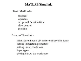
1 / 17
640 likes | 1.78k Views
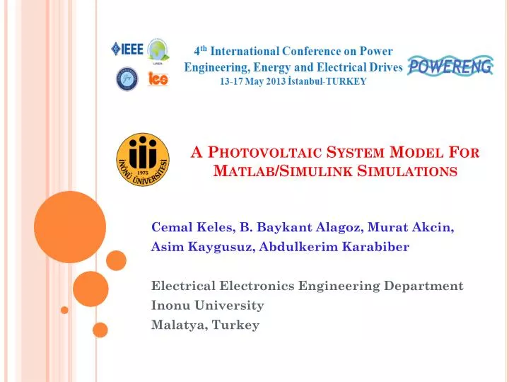
A Photovoltaic System Model For Matlab /Simulink Simulations. Cemal Keles, B. Baykant Alagoz, Murat Akcin, Asim Kaygusuz, Abdulkerim Karabiber Electrical Electronics Engineering Department Inonu University Malatya, Turkey. V L. V m , I m. I L. Behavioural PV Model.

E N D
A Photovoltaic System Model For Matlab/Simulink Simulations Cemal Keles, B. Baykant Alagoz, Murat Akcin, Asim Kaygusuz, Abdulkerim Karabiber Electrical Electronics Engineering Department Inonu University Malatya, Turkey
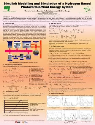
VL Vm, Im IL Behavioural PV Model Power-limited Electrical Driver Load PhotovoltaicSystem Model • This study aims to developed a general propose Simulink PV module • The proposed model is based on a behavioral cell model and an electrical driver interface: • A behavioral cell model is for solar radiance to electrical parameter conversion. • An electrical driver interface is for implementing electrical characteristic of power limited systems in power simulations PV Simulation Model
Behavioral PV Modeling • The overall current, which the PV cell can provide, was formulated by • The voltage of PV cell was formulated by • Vmis the output voltage, and Im is the output current • Nsc and Npc are expressed numbers of series and parallel connected PV cells
Behavioral PV Modeling • Simulink schema for behavioral PV model
Power-limitedElectricalDriverModeling • There is need for an electrical driver component that exhibits an I-V characteristic complying with the response of PV panels • Power-limited electrical driving of the electrical loads is implemented in the form of modified sigmoid function given by • The parameter φ is used to adjust decline of panel voltage Vg against the increase of load current IL
Power-limited Working Region of Electrical Driver PmVmIm MMP Power-limitedElectricalDriverModeling • This function can approximate to limited power I-V characteristic of PV panels for Im=0.5, Vm=1.5, and φ=20 as illustrated in
Power-limitedElectricalDriverModeling • Figure shows simulink model of the power limited electrical driver • Ri represents internal resistance between metal contacts of silicon layers and panel output ports • Cirepresents internal capacitance caused from capacitivestructures in the panel • These are used to configure transient response of PV module
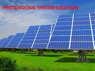
SimulationExamples • The module parameters were mainly configured according to Solarex MSX60 specifications for solar radiation of 1000 W/m2 and cell temperature of 25oC • Parameter settings are listed in table
SimulationExamples • Tests for Constant Resistive Load • Figure shows a Simulink simulation of the proposed PV module connected to a DC resistive load • The load resistor RL was set to 4.5 Ohm for working nearby MPP • A reference radiation (G) of 1000 W/m2 and module temperature (Tc) of 25oC were used • The internal resistor Ri and capacitor Ci were set to 1 Ohm and 10-2 F, respectively
(a) (b) (c) SimulationExamples • Tests for Constant Resistive Load • Transient response of PV module, when connected to the resistive load, is illustrated in Figure
(b) (a) MMP MMP SimulationExamples • Tests for Constant Resistive Load • Figure demonstrates power injection of PV module for various values of load and load voltages • MMP points indicates power limits of PV modules • This is very useful for testing MPP tracking methods in Matlab/Simulink
Discrete , Cur Ts = 5 e - 005 s . Va + powergui V + Va - V - i + - Measurement Current Measurement 25 V + T A T DC V + Ra B Diode 1000 V - G DC V - C G DC / AC Converter PV Model Rb Rc SimulationExamples • Solar Power For Three Phase AC Power Distribution Simulation • Simulink simulation of a PV array supplying three phase AC distribution system is shown in Figure
SimulationExamples • Solar Power For Three Phase AC Power Distribution Simulation • The DC/AC converter with PWM three arms IGBT inverter causes DC instability due to periodical switching of PV module current • In order to reduce negative impacts of possible reverse current of DC/AC converter on PV module, a diode is used • Output of PV module is connected to DC/AC converter to supply 1000 Watt resistive loads per phase • In order to draw adequate power from PV module, Nsc=10 and Npc=5 were configured for the PV module
SimulationExamples • Solar Power For Three Phase AC Power Distribution Simulation • Figures show average magnitude of the power (PL) drawn from PV module, DC voltage (VP) supplied from PV module,andline to neutral AC voltages measured from resistive loads, respectively • After a transient regime continuing 0.1 second, average power drawn from PV module goes into steady regime and settles roughly at 3000 Watt (c) (a) Transient Regime Steady State Regime (b)
Conclusions • This study presents a general purposes PV simulation module and its application examples in Matlab/Simulink simulation environment • This PV model is easy to configure for a desired PV response characteristics • This model directly connects to SimPowerSystems electrical circuits. • The PV module has two main parts: A behavioral model of PV cells and a power–limited electrical driver for circuit connection • The behavioral model estimates voltage and current potential of PV panel for a given solar radiation (G) and module temperature (Tc) conditions • The power–limited electrical driver implements a relevant electrical response on the load
Conclusions • The proposed PV module can be employed in transient analysis of power system supplied with PV panels • This model is also useful for testing MPP tracking methods • Nowadays, solar energy integration in microgrids is becoming primary concern of power system industry. Modeling renewable energy sources for a large-scale power system integration simulation is more important today. Because these simulation tools will be a part of optimal design and intelligent management process