Download

1 / 27
280 likes | 561 Views
Fixed voltage 1 or 3- phase ac. Fixed voltage 1 or 3-phase ac. Fixed voltage dc. Variable voltage dc. Diode rectifier. Fully controlled thyristor rectifier. Fixed voltage dc. Fixed voltage 1 or 3- phase ac. Variable. Fixed voltage 1 or 3- phase ac. Rectifier with Self Commutated

E N D
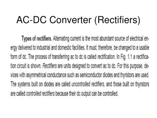
Fixed voltage 1 or 3- phase ac Fixed voltage 1 or 3-phase ac Fixed voltage dc Variable voltage dc Diode rectifier Fully controlled thyristor rectifier Fixed voltage dc Fixed voltage 1 or 3- phase ac Variable Fixed voltage 1 or 3- phase ac Rectifier with Self Commutated devices Diode rectifier chopper Variable Voltage dc Voltage dc AC-DC Converters or Rectifiers Variable Voltage ac Fixed voltage 1 or 3- phase ac Fixed voltage 1 or 3- phase ac Transformer with taps Diode rectifier Variable Variable voltage dc Half-controlled thyristor rectifier Voltage dc
f Fixed voltage Amplidyne variable 3-phase ac Voltage dc Fixed voltage ac Diode rectifier Variable voltage dc Variable voltage dc Ac motor Ac motor Dc generator Fixed voltage Magnetic amplifier Diode rectifier variable 1 or 3-phase ac Voltage dc
Autotransformer Of fixed turns ratio Fixed voltage Lower (fixed) 3-phase ac Ac voltage Thyristor voltage controllers Fixed voltage variable 3-phase ac Voltage ac Magnetic amplifier Fixed voltage variable 3-phase ac Voltage ac Ac voltage controllers Transformer with taps Fixed voltage variable 3-phase ac Voltage ac
Semiconductor chopper variable Fixed voltage dc Voltage dc
Filter l d chopper Six step inverter L IM DC supply C V d Dc link Filter Filter Filter l l l d d d chopper Diode bridge Six step inverter PWM inverter PWM inverter L L L AC supply AC supply IM IM IM C C C V V V d d d Dc link Dc link Dc link DC supply
L d CSI CSI V V d d chopper DC supply Induction motor Dc link Fully controlled rectifier AC supply Induction motor Dc link
L l d d T T T 5 1 3 3-phase V ds V dl Ac supply Synchronous motor T T T 4 6 2 Source side converter Load side converter
wm wm Tc Tv Ts o o Ts Tor que TF Tc Tv
+ w T L o +T -T -w
w w m m o T l o T l
p p t t
p p t t
Forward motion Reverse motion
P P t
Viscous Dry Fan IL Motor Friction v Friction w wL
L T m v
P= f (N) N P 1 P 2 N= f (t) P= f (t) P, t t t 2 1
T T1 II Forward Motoring Counterweight Counterweight Empty cage Loadedcage III Reverse Motoring Counterweight Counterweight Empty cage TL I TL Load torque with loaded cage Load torque with empty cage IV Loaded cage
TL Motor Load TM Fig. 2.10. Motor- load system
M V W Fig. 2.12 Motor-hoist load system
TL TL Stiction +i -T -T TL Fig. 2.2. Speed torque curve of dry friction load Fig. 2.3. Speed torque curves of Viscous friction load.
+ + -T -T +T +T - - Fig. 2.4. Speed torque curve of a fan type load. Fig. 2.5. Speed torque curve of a constant power load
2 h 1 W F Fig.2.7. Hoisting .mechanism Fig.2.6. Forces during the upgradient motion of a train,
TL n Jn, J2, 2 J1, in 1 i2 M i1 N Fig.2.11. Motor-Load system with gears.
TL ONE PERIOD Fig.2. 8. Speed-torque characteristic of a reciprocating compressor.