Download
1 / 35
360 likes | 631 Views
X-Band Deflectors. V.A. Dolgashev, SLAC National Accelerator Laboratory. 2 September, 2010 ICFA Beam Dynamics Mini-Workshop on Deflecting/ Crabbing Cavity Applications in Accelerators Cockcroft Institute, 1-3 September 2010. Acknowledgments. I want to thank all contributors to this report:

E N D
X-Band Deflectors V.A. Dolgashev, SLAC National Accelerator Laboratory 2 September, 2010 ICFA Beam Dynamics Mini-Workshop on Deflecting/ Crabbing Cavity Applications in Accelerators Cockcroft Institute, 1-3 September 2010
Acknowledgments I want to thank all contributors to this report: • Graeme Burt of Cockcroft Institute, Lancaster University • Joel England of SLAC and previously of UCLA • Jake Haimson of Haimson Research Corporation • Alex Murokh of Radiabeam Technologies • PietroMusumeci of UCLA • Juwen Wang, Gordon Bowden, Robert Reed of SLAC • Craig Wilsen of L3 Communications
Outline • Introduction • SLAC 11.4 GHz traveling wave (TW) deflector for Linac Coherent Light Source (LCLS) • Radiabeam Tech. 11.4 GHz TW deflector for BNL Accelerator Test Facility (BNL-ATF) • The Cockcroft Institute / Lancaster University TW deflectors for linear collider • 11.4 GHz prototype for high power tests • 12 GHz • UCLA 9.6 GHz standing wave (SW) deflector • Hiamson Research 17 GHz circularly polarized SW deflector • New X-band rf power sources
Introduction Why X-band for rf deflectors? • Compact • Practical devices that allow extreme timing resolution, such as ~10 fs at 14 GeV • Practical way to build portable ~fs beam diagnostics for ~MeV beams Difficulty: Need expensive rf power sources, from 0.1 to 10th MW of X-band rf power
11.424 GHz Traveling Wave Deflector for LCLS J. Wang et al., SLAC
Regular Cell, HFSS Model J. Wang et al., SLAC
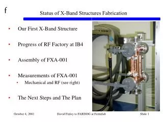
Annealing of Cups for Final Machining J. Wang et al., SLAC
Waveguide Coupler for TW X-band Deflector,20 MW of Transmitted Power, or 21.3 MeV kick for 89 cm structure Maximum surface magnetic fields ~400 kA/m, Pulse heating 22 deg. C for 100 ns pulse. Maximum surface electric fields ~100 MV/m. V.A. Dolgashev, Waveguide Coupler for X-band Defectors, Advanced Accelerator Concepts Workshop 2008, Santa Cruz, CA, July 27 – August 2, 2008: http://www.slac.stanford.edu/~dolgash/x-rays/Waveguide%20coupler%20for%20an%20x-band%20defector%20Dolgashev_AAC08_31jul08.pdf
Input/Output Couple Assemblies Completed Couple Assembly Mechanical Design Model J. Wang et al., SLAC
Application: 10 fs Time Resolution for 13.6 GeV LCLS Beam P. Emma, An X-Band Transverse RF Deflector for the LCLS, Oct. 18, 2006 Table 1. Parameters for a 10-fs temporal resolution using an X-band RF deflecting cavity. SLAC XL-4 Klystron, 50 MW, <1.6 us 3 dB splitter Table 3. Approximate specifications for an X-band RF deflecting cavity. 20 MW 100 ns 20 MW 100 ns Kick 42.6MeV bunch 13.6GeV ~190 cm
11.424 GHz Traveling Wave Deflector by Radiabeam Technologies A . Murokh et al., Design and Fabrication of an X-band Traveling Wave deflection Mode Cavity for Longitudinal Characterization of Ultra-Short Electron Beam Pulses, Proc. Of EPAC08, Genoa, Italy, 2008, pp. 1215-1217 A . Murokh, Radiabeam Tech.
Manufacturing • Adapted SLAC cleaning and handling procedures developed for high gradient X-band structures A . Murokh, Radiabeam Tech.
Bead pull Test of Clamped Structure at SLAC Fields measured along axis A . Murokh, Radiabeam Tech.
Application: Measurements of Longitudinal Phase Space of BNL ATF Beam Longitudinal resolution should be better than 10 fs for beam energy 75 MeV and transverse emittance ~2 um. 100 fs Numerical (ELEGANT) model of ATF X-band deflector experiment: a post-compressor beam longitudinal phase space in (p,t)-coordinates (X,Y) map after the rf deflector and a bending magnet A . Murokh, Radiabeam Tech.
11.424 GHz TW Deflector Prototype for Linear Collider CLIC There are plans to test this prototype at SLAC to study high power aspects of its operation. G. Burt et al., X-band crab cavities for the CLIC beam delivery system, Proceedings of X-Band Structures and Beam Dynamics Workshop (XB08), Cockcroft Institute, UK, 1-4 dec. 2008, arXiv:0903.2116v1 G. Burt, The Cockcroft Institute / Lancaster University
11.424 GHz TW Deflector Prototype for Linear Collider CLIC, HFSS Model for Two Regular Cells With Couplers Maximum surface electric field ~90 MV/m Maximum surface magnetic field ~350 kA/m, pulse heating 24 deg. C for 200 ns pulse Fields for 20 MW of transmitted power G. Burt, The Cockcroft Institute / Lancaster University
11.424 GHz TW Deflector Prototype for Linear Collider CLIC Coupler parts Solid model G. Burt, The Cockcroft Institute / Lancaster University
12 GHz TW Deflector for Linear Collider CLIC G. Burt, The Cockcroft Institute / Lancaster University
Application: Crab Crossing Using RF Deflectors Near Interaction Point in a Linear Collider Ref.: R. B. Palmer, Energy scaling, crab crossing and the pair problem, SLAC-PUB-4707, 1988 RF deflector • RF deflector is placed in each beamline • Cavity is phased that there is no net deflection at the interaction point, the bunch rotated aroundits centre Operation of the rf deflectors for the crab crossing puts tight requirements on phase and amplitude jitter between both deflectors and on wakefield damping. In case of 12 GHz deflector the jitter has to be <2.1% for amplitude and < 0.018 deg. phase. G. Burt, The Cockcroft Institute / Lancaster University
9.6 GHz SW deflector at UCLA R. J. England et al., X-Band Dipole Mode Deflecting Cavity for the UCLA Neptune Beamline, in Proc. of PAC 2005 , Knoxville, Tennessee R. J. England, SLAC/UCLA
Design Evolution 2006 2004 2005 cold test prototype steel prototype final design Aluminum 9-cell 9.3 GHz cold-test only clamped no polarization separation Steel with Cu coating 9-cell 9.5 GHz cold-test only conflatflange design no polarization separation GlidCop Al-15 9-cell 9.59616 GHz tested up to 50kW peak power conflatflange design EDM’ed polarization holes R. J. England, SLAC/UCLA
Final Cavity Design • 9-cell standing wave structure • center-fed input rf • reconditioned 50 kW VA-24G klystron • no brazing between cells • cells are stacked ConFlatvacuum flanges one cell with polarization holes X-band klystron (50 kW peak) R. J. England, SLAC/UCLA
Application: Measurement of Longitudinal Phase Space P. Musumeci, UCLA
Application: Measurement of Longitudinal Phase Space • Measurements of 3.5 MeV beam: • Time resolution is 50 fs • Energy resolution is 1 keV, determined by energy spread introduced by rf deflector J. T. Moody et al., Longitudinal phase space characterization of the blow-out regime of rfphotoinjector operation, Phys. Rev. STAB 12, 070704 (2009) Very linear phase space High 6D beam brightness Ultralow longitudinal emittance (<0.5 um) Longitudinal phase space measurement compared with simulation. Bunch charge 20pC, 500 micron rmslaser spot size on the cathode. P. Musumeci, UCLA
Application: Single Shot Ultrafast Electron Diffraction (UED) 50/100 mm movable slit diagnostic screens diffraction target solenoid Faraday cup dipole gun quadrupoles mirror box RF deflector P. Musumeci et al., Relativistic electron diffraction at the UCLA Pegasus photoinjector laboratory , Ultramicroscopy, Volume 108, Issue 11, October 2008, Pages 1450-1453 P. Musumeci, UCLA
Application: Single shot Ultrafast Electron Diffraction • Use RF deflecting cavity as a streak camera to time-resolve a relatively long (10s of ps) electron beam after its interaction with the diffraction sample. • Advantages • Eliminates limitation of the time resolution due to the length of the electron beam and therefore significantly improves the temporal resolution of the technique. • Yield true single-shot structural change studies revolutionizing the approach of the conventional pump-probe experimental procedure. By using an X-band deflector powered by 5 MW X-band klystron the Ultrafast Electron Diffraction could be done with <5 fs resolution Detector screen Crystal Sample y x z Dp Diffracted beam Deflected beam E- beam x y∼t RF deflector Laser pump pulse P. Musumeci, UCLA
17 GHz circularly polarized SW deflector by Haimson Research Corporation Advanced Accelerator Concepts, AIPConferenceProceedings, 647, (New York: AIP Press, 2002) , pp. 810-820 Advanced Accelerator Concepts , AIPConferenceProceedings, 737, (New York: AIP Press, 2004), pp. 95-108 J. Haimson, Haimson Research Corporation
Method S-Band RF Bunch Measurements Using a Circularly Scanned Beam (2 x TE102 Rectangular Cavities With Transverse Magnetic Fields) J. Haimson, High Current Traveling Wave Electron Linear Accelerators, In Proc. of PAC 1965, Washington DC, March 1965, pp. 996-1011 J. Haimson, Optimization Criteria for Standing Wave Transverse Magnetic Deflection Cavities, Proc. of 1966 Linear Accelerator Conference, LA-3609, Los Alamos, 1966, pp. 303-331. J. Haimson, Haimson Research Corporation
17 GHz Circularly Polarized RF Deflector Designed for Displaying the Longitudinal Phase Space of 1 Degree Electron Bunches from a 17.136 GHz 15 MeVLinac J. Haimson, Haimson Research Corporation
Application: Measurement of Longitudinal Phase Space Typical electron bunch longitudinal phase space displays obtained with near optimum chopper-prebuncher operation of the 17 GHz linac, showing the energy and phase charge distributions as the injector controls were adjusted to reduce the bunch length by a factor of 5. J. Haimson, Haimson Research Corporation
Application: Measurement of Longitudinal Phase Space 15 MeV, 1.7°Linac Bunch After Circularly Polarized Deflection and Transmission Through a Matrix of Precision Collimators J. Haimson, Haimson Research Corporation
Recently advertised commercial 9.3 GHz klystrons CPI-VKX-7993 L3-L-6145 A. Balkcum et al., Design and Operation of a 2.5 MW, PPM Focused X-Band klystron, In Proc. of IEEE International Vacuum Electronics Conference, Rome, Italy, April 28-30, 2009 Mark Kirshner et al., High Power X-Band Klystron, In Proc. of IEEE International Vacuum Electronics Conference, Rome, Italy, April 28-30, 2009
Summary • X-band deflectors are used for beam manipulations, fs beam diagnostics, and novel methods in ultrafast physics • Development of new rf deflectors utilizes mature high gradient X-band technology • Introduction of commercial X-band klystrons opens new possibilities for practical applications of the rf deflectors